This topic is locked

PERFECT CURVES AND LOOP (2 in 1 Tut)
© Copyright 2011, this thread is not to be copied, used or sold for commercial purposes or financial gain without the author or www.SS.Coasters.net consent.
Foreword
This is my first tutorial and I’m a first time builder and I’m in the middle of building my first custom build coaster. So you may think that it is arrogant of me to even think about posting a tutorial on here.
For me the most difficult thing as a novice builder was to get perfect curves and the shaping right. After a few failed attempts to get the shaping right, even though after a few attempts I was getting better, I still wasn’t 100% happy with the shape of my first drop.
Whilst staring at my K’nex Ferris wheel, the answer to my problem was staring me right in my face and I decided to create me own method for getting those perfect curves.
I put my method to the test and then I found that I was getting quicker and better results with regards to shaping, so I decided to share my method with you all.
I hope that you all will find this thread of interest and I hope that my method will help other novice builders like myself to get off to a better start.
In demonstrating how to use my method, I’m going to show you how I built and shaped my loop. But I also eventually used this method for the crest of the lift hill and my first drop.
The method show is used in conjunction with Tube supports, but this method can also be used with a box type frame.
I must also point out that I have only used this method for straight drops and loops, but I am unsure if my method could be used or adapted to be used for curved drops and cork screws.
I hope you enjoy!
The Method
What you will need. Sorry I haven’t done any parts count, for the simple reason is that each and every build will be different. You will need a good variety of rods, connectors and spacers.
Step 1. Take an 8 Way Connector.

Step 2. Add 5 Rods.

Step 3. Keep extending the Rods until you have the right size radius for the top of your loop. Or you can use shorter Rods for a small radius curve. Or a combination of sizes of Rods and connetors to get your ideal size radius curve. The most important thing is to make sure that the total length of each spoke is exactly the same length.
Step 4. Now add to the end of each spoke, a connector and a 32mm size rod. I’m going to refer this to as the “semi circle spoke curve.”

Step 5. Now for the curves in and out of the loop, again take an 8 Way Connector and add 3 Rods. You should only need to make one of these.

Step 6. Extend this rods using a combination of ladder connectors and rods until the desired size radius. The radius of these curves should be bigger than the radius for the top of the loop. Again make sure that all the spokes are the same lengths.

Step 7. Add an orange ladder connector and a 32mm rod to the end of each spoke.

Step 8. Add the Blue 7 Way 3D Connectors as shown. Make sure that these are connected exactly as shown. I’m going to refer to this as the “quarter spoke curve”

Purely for the purpose of demonstration, I have laid the one of the spoke curves over the top of the other; along with some green crossties connectors to show the route of your track. You don’t need to do this.

Again purely for the purpose of demonstration and you do not need to do this, I created a second quarter spoke curve. I laid this on top of the previous photo to show you the complete route for the track for the completed track. The track tubing will follow the path of where the outer orange connectors are connected to the long grey rods and the blue connectors will show you where you will connect the track to the Tube supports or Box type supports.

And I have also added the green crossties to show you the route of the track, again you don’t need to do this, I’ve done this to purely show you how the spoke curves work.

Now I’m going to show you how to turn this flat model into the real build.
Step 9. Take the quarter spoke curve and add 3 more Blue 7 Way 3D Connectors to all the other Blue 7 Way 3D Connectors as shown.

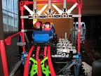
Step 10. The Blue Connectors shows exactly where the tops of your tube supports should meet the track. Hold the quarter spoke curves in a vertical position, with one of the end spokes pointing downwards, the other end spoke pointing horizontal and the spoke in the middle pointing downwards at a 45 degree angle. Now build your tube supports from the Blue Connectors to the floor as shown. I haven’t given you instructions on how to build the tube supports as these can be found for free on the Screamin' Serpent Coasters - K'NEX & CoasterDynamix Models website. I recommend MP Thrill Rides – Tube Supports. You will need to register and log in to view the tutorials threads. When building your tube supports or fixing points, it is important that you ensure that the spoke are evenly spaced.


Step 11. Disconnect the spokes from the Blue connectors but do not completely dismantle the quarter spoke curve as you will still require this. The quarter spoke curve is now missing its Blue Connectors and you will need to replace these again with some new Blue Connectors as in steps 8 and 9.
Step 12. Hold and fix the semi circle spoke curve in place as a guide to show you where to positioning of the quarter spoke and tube support for the second half of the loop should go.

Step 13. You will also need to add two blue 3D connectors to the other end of the semi circle spoke curve.

Step 15. Build a tube support from this connector.

Step 16. Remove the semi circle spoke curves from the blue connectors, but do not dismantle the semi circle spoke curve as you will need this later on. Repeat steps 10 and 11 to build the supports for the second half of the loop. The photo shows you the tube supports with the quarter spoke curve in place. Again you will need to remove the quarter spoke curves from the blue connectors, but do not dismantle the quarter spoke curve as you will still need to use this later on.

Obviously, when you build the second half of the loop, you can use the first half of the build to copy, and then simply turn the build 180 degree around and then place it beside the first build. You will need to remove the k’nex parts at the base from one side of the build where they meet and join them together.

Step 17. Using small Rods add green crossties add to the Blue Connectors.

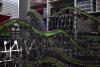
Step 18. Add the track and use one of the track strengthening methods which can be found for free on Screamin' Serpent Coasters - K'NEX & CoasterDynamix Models website. I recommend using RCExtreme - My Super Strong Track Strenghteners. The next photo shows a cross section of the track section.

Step 19. Use the spoke curves as tools to check and shape the loop, you may wish to keep these for future use to check the shaping from time to time. Don't forget that the outer orange connector where it joins the long grey rods is where the purple tubing runs and not the very ends of the spokes. If out of shape, adjust the shape, this can be done by simply bending the track, adjusting the crossties or you may need to move the fixing point where the track connects to the supports over to the next crosstie.


Step 20. Take a photo, the photo will show up any flaws, sharp or straight spots which can easily be missed with the naked eye.
If you need more fixing points especially if you are building a box type frame or just to check the curves, in addition to what you have done, simply rotate the spoke curve back and forwards to measure radius in-between the fixing points or to create more fixing points.
This method can be used for drops etc…
Below are a couple of examples of spoke patterns that you can use. For different size curves, just use different length spokes. If you take a closer look, the connectors at the crest of the hill are on the inner side, this is where you connect the track to the supports and the orange connector either where they join to the long grey rods or joined to nothing is where the track tubing will run.


 SSCoasters Staff