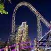
S&S Space Shot model powered by compressed air
Soon I’ll be attempting to build another tower ride. But not just any; this will be an S&S Space Shot, which will actually be powered by compressed air (which is, as far as I know, an unpaved path in k’nex world). The reason I decided to take this project on, is that I did some calculations and found out that itactually doesn’t take a lot of pressure to power this, meaning that leakage will be a relatively small problem. Also, pneumatics parts aren’t expensive at all and mechanically there isn’t that much going on to further complicate things.
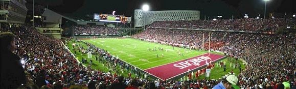
The S&S Space Shot
The Space Shot is a tower kind of attraction, which makes use of compressed air to shoot riders into the air. Countless of these rides were installed throughout the world and they were ultimately the beginning of S&S Entertainments success, thanks to their incredible smoothness and reliability.
Scaling it down
When a model of an existing thrill ride is being made, the builder often finds himself battling against the laws of physics: You can scale a ride down as perfectly as possible but some physical principles, including gravity, do not always scale so well. This results in chair swing rides that do not swing out at all unless driven at insane speeds, or rollercoaster tracks that have an effective ride time of about 5 seconds. By analysing the underlying physical mechanism of a ride, it is possible to anticipate any scaling problems and maybe even adjust your system.
All of this can be applied to the Space shot. The trajectory of the ride exists of a damped oscillation, of which the equilibrium position actually moves down (due to leaking which may or may not be on purpose). I imagine that for some, that sentence might need some more explanation.
The system of this ride can be described by two tubes, one being the pressure tank and the other one being a tube with one end connected to the pressure tank and the other end open. In this second tube, which will be called the cylinder from now one, a piston is inserted. When the air pressure on one side of the cylinder is higher than the other side, it will try to compensate for this by moving towards the lower air pressure. In the following figure, schematics of the system are shown.

A) In this setting, a valve (black bar at the top of the drawing) prohibits the pressurised gas in the pressure tank (left) to escape to the cylinder (right).
 Now, the valve is released. At this point, the pressure above the piston (the white box in the right cylinder) exceeds the atmospheric pressure underneath the piston, causing it to move downwards, pulling up the car, illustrated by the little white box attached to the wire.
C) At this point, the movement of the piston has compensated for the over-pressure. The car however is still moving, and its momentum causes the piston to move even further, causing a vacuum in the system.
D) Right now, the vacuum (which means the pressure is lower than the atmospheric pressure) inside the cylinder causes the piston to move upwards. This way, the riders experience a downwards force which is actually greater than the gravitational force alone (which explains the measurements done in this website, which say that the downwards acceleration exceeds g = -9.81 m/s^2).
E) Again, the moving piston has compensated for the pressure difference, but the car’s momentum causes it to move even further, after which it ends up in situation B, and the cycle will go on like this.
Using this, one can now simulate the system for different variables (for instance length of tower, maximum pressure used, diameter of the cylinders etc. Using MATLAB, I created a script which plots the motion, speed, acceleration etc. through time, for certain set variables.
The essential ones are:
p_init, the initial pressure in the pressure tank
m_car, the mass of the car
m_counter, mass of the counterweight
R_cilinder, the radius of the cylinder
R_tank, the radius of the pressure tank
L_tower, the length of the tower
There are some principles in choosing the right values, but I won’t get into this much further. Imagine a case where certain variables are already given, for instance, you have chosen to make a 1.5 meter tall tower, the tubes you use will be 8mm and 18mm in diameter, the car has a mass of 0.4 kg and the counterweight weighs 0.3 kg. By trial and error (although this could also be programmed), you can then find out that using an initial pressure of 1.3 bar will cause the following oscillation, which is perfect because it reaches the 1.5 m top just fine! The graphs according to the script are shown below.

Below you can see graphs that are based on measurements on a real Space Shot, which experiences friction and pressure drop due to leakage. These were found on the previously mentioned website and were measured on the Space Shot in the Linnanmäki Amusementpark using accelerometers.

As you can see, it doesn't look much like the previous graphs that were simulated. This is due to friction and leaking that were not taken into account. By adding a leak-parameter (which is given in Pa/sec for convenience) and an airresistance-parameter. Adding these into the program and changing them around a bit (which isn’t quite scientific, but hey…) shows how the simulation can actually very closely describe the motion of the real thing.

Compare the Position vs. Time graph of the real thing, to the Height vs. Time graph of the simulation.
As you can see, the settings shown above actually allow a life-like motion of the ride. It now takes around 3 sec to reach the top, which is very comparable to the real thing. And this was, ultimately, the goal of this entire analysis.
Implementation
The things I bought are a 12V solenoid valve, which is basically just an “air-switch”, a barometric pressure sensor which connects to an Arduino and a 12V air pump which runs at 0.5A. These parts arrive in a few weeks so I’ll be experimenting with them then.
The construction will exist of a standard kind of drop tower (much like the Power Tower 2.0), only in the center there will be two PVC tubes which will function as cylinder and pressure tank. I’ll have to experiment a bit with building a piston and stuff like that, but if all goes well it should be a very simple build.
The ride program should be as follows:
Due to minor leaking, the car will always be at the bottom if you wait long enough, so when the program begins the car is always at the bottom. The solenoid valve is closed, and the air pump is started, which pressurizes the pressure tank until the pressure sensor measures the right pressure is reached. Then the pump stops, and when desired, the valve is opened and the car is set in motion. When the car has returned, the process repeats.
That's it! I plan on finishing the electronics soon after the pneumatics parts arrive. During christmas break I hope to be able to build the tower and implement all the pneumatics.
If you're interested in this project, please subscribe because the updates wont be very frequent and I wouldn't want you to miss anything.
If you have questions, remarks, or maybe even some better resources than I did, please tell me!
Also, a few assumptions were made about the S&S Space Shot. There isn't much information available on the internet, so if I said anything wrong, please correct me!
Greetings,
Suck
Edited by TheSUCKCrew, 04 November 2015 - 11:35 AM.