Hello everyone and welcome the the GKD.
This topic will be a collection of all the important guides/examples/... concerning electronics and the arduino in general.
Please post comments in the General Electronics Forum. As there is a specific sub-forum for electronics now, larger problems or projects can be discussed in separate topics.
Contents:
General:
1. Introduction to electronics
2. The transistor
Arduino:
3. Outputs
4. Programming
5. Sequential control
General Knowledge Database
Started by
floris2burn
, Apr 15 2011 11:17 AM
5 replies to this topic
#2

floris2burn
-

- 414 posts
Software Engineer
Posted 15 April 2011 - 11:17 AM
1. Introduction to electronics
1.1. Rules for determining Voltage, Ampère and Resistor
Ohms Law:
R = V/I
Where
Components in series:
Components in parallel:
Conclusions
1.2. Examples
Series: LED's and resistor
LED at 2.1V and 20mA (datasheet)
Vsource = VLEDs + Vresistor
Vresistor
= Vsource - VLEDs
= 12V - (5 * 2.1V)
= 1.5V
Use Ohms Law:
R = 1.5V / 0.02A
R = 75 Ohms
Best available resistor (E12 series): 82 Ohms
Actual current:
I = U / R
= 1.5V / 82Ohms
= 0.0183A
We take a resistor that's larger than what we calculated so we don't overload the components. Because the more resistance, the less current.
Parallel: LED's and resistor
Continuing from the previous example, we add 2 more identical branches next to the original.
Current needed from the Power Supply:
3 branches in parallel at 20mA give
Itotal = 3 * 20mA = 60mA
1.3. Recognize your LED
Original article from Maxlaam 12-28-2010, 02:21 PM
1.1. Rules for determining Voltage, Ampère and Resistor
Ohms Law:
R = V/I
Where
R is the resistance in ohms.
V is the potential difference in volts.
I is the current in amperes.
Components in series:
Vtotal = V1 + V2 + V3 + ...
Itotal = I1 = I2 = I3 = ...
Rtotal = R1 + R2 + R3 + ...
Components in parallel:
Vtotal = V1 = V2 = V3 = ...
Itotal = I1 + I2 + I3 + ...
Rtotal = 1 / (1/R1 + 1/R2 + 1/R3 + ...)
Conclusions
- If components are wired in series, each component will have a certain voltage drop. Where the current trough all these components will be the same.
- If components are wired in parallel, each component will receive the same voltage, but the total current drawn will be the sum of all the individual currents.
1.2. Examples
Series: LED's and resistor
LED at 2.1V and 20mA (datasheet)
Vsource = VLEDs + Vresistor
Vresistor
= Vsource - VLEDs
= 12V - (5 * 2.1V)
= 1.5V
Use Ohms Law:
R = 1.5V / 0.02A
R = 75 Ohms
Best available resistor (E12 series): 82 Ohms
Actual current:
I = U / R
= 1.5V / 82Ohms
= 0.0183A
We take a resistor that's larger than what we calculated so we don't overload the components. Because the more resistance, the less current.

Parallel: LED's and resistor
Continuing from the previous example, we add 2 more identical branches next to the original.
Current needed from the Power Supply:
3 branches in parallel at 20mA give
Itotal = 3 * 20mA = 60mA

1.3. Recognize your LED

Original article from Maxlaam 12-28-2010, 02:21 PM
![]()

#3
floris2burn
-
- 414 posts
Software Engineer
Posted 15 April 2011 - 12:08 PM
2. The transistor
2.1. The transistor has 2 purposes
The second purpose is mostly for things like audio and video transmitters or amplifiers. These involve the use of the hFE value.
The first one on the other hand is about getting the transistor in saturation, which will "close the switch".
If you use transistors as switches, you need to make sure you don't overload it:
When using LED's, don't forget the resistors.
When using other components, try to figure out the current it will need and the current the transistor can endure.
On the other side, the Base-Emitter also needs protection, because there's no resistance here either. Calculate the resistor by looking up the IB and VBE value.
Side note: if you need help calculating the resistors, check the internet or ask me.
2.2. NPN <> PNP
What's the difference? The internal structure of the Positive and negative layers. (I don't know the terms for all these things so I won't go into detail).
Still, what's the difference? You connect them differently!
(note the difference in symbol.)
To all the people who want to use microcontrollers, I suggest using NPN transistors, so it's easier to use different voltages on the secondary (load) side.
Go to the original post.
2.1. The transistor has 2 purposes
- As switch
- As amplifier
The second purpose is mostly for things like audio and video transmitters or amplifiers. These involve the use of the hFE value.
The first one on the other hand is about getting the transistor in saturation, which will "close the switch".
If you use transistors as switches, you need to make sure you don't overload it:
When using LED's, don't forget the resistors.
When using other components, try to figure out the current it will need and the current the transistor can endure.
On the other side, the Base-Emitter also needs protection, because there's no resistance here either. Calculate the resistor by looking up the IB and VBE value.
Side note: if you need help calculating the resistors, check the internet or ask me.
2.2. NPN <> PNP
What's the difference? The internal structure of the Positive and negative layers. (I don't know the terms for all these things so I won't go into detail).
Still, what's the difference? You connect them differently!
(note the difference in symbol.)
NPN on the left; PNP on the right

To all the people who want to use microcontrollers, I suggest using NPN transistors, so it's easier to use different voltages on the secondary (load) side.
Go to the original post.
![]()
#4
floris2burn
-
- 414 posts
Software Engineer
Posted 15 April 2011 - 12:18 PM
3. Outputs on the arduino
Today I'd like to talk about using the outputs on an arduino.
There will be 3 possibilities depending on your load.
3.1. The load
Naturally, you'll have to determine the load first. This can either be done by looking up the datasheet, using a multimeter or calculating your way out of it.
Examples:
3.2. Voltage range
But this is only one half of the story. The output of an arduino pin only has a potential difference of 5V. If you wish to alter from this, you already have to use additional switching elements.
Now, let's proceed.
3.2.1. Loads up to 40 mA
3.2.2. Loads up to about 600mA
3.2.3. Loads up to about 2A (2000mA)
3.2.4. Loads above 2A
Are you sure? Check again, distribute your load or you'll have to reconsider working with a regular circuit board.
WARNING: What's mentioned above is a guideline. You always have to check the datasheet for the maximum load for the specific element you have or want to use. A small difference in ID-number can result in a very different element.
3.3. Connecting
Transistors are used like switches. To control it, you need to send a signal to the base pin, or pull it to the ground if the switch has to be open.
This is done by attaching the base pin to the output pin and also installing the right resistor.
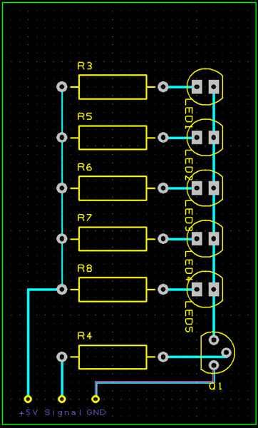
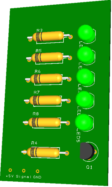
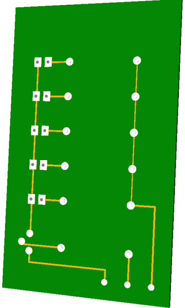
3.3.1. Example one: Transistor, 5 leds on the +5V pin. (if each draw 20-30mA, the total load current would be 100-150 mA)
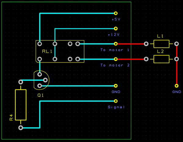
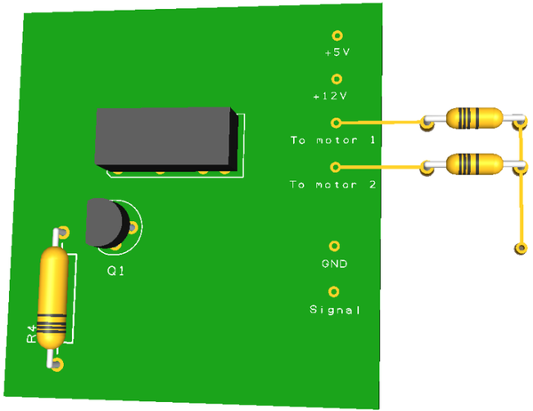
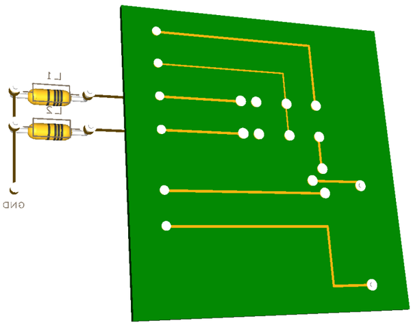
3.3.2. Example two: 5V Relay switches 2 motors. The current of the relay is too high for the output pin, so it has to be switched with a transistor.
(The DC motors are represented by a coil, in 3D they're the small resistors outside the green circuit board.)
Image gallery: Link.
Schematics have been made with DesignSparkPCB
Go to the original post.
Today I'd like to talk about using the outputs on an arduino.
There will be 3 possibilities depending on your load.
3.1. The load
Naturally, you'll have to determine the load first. This can either be done by looking up the datasheet, using a multimeter or calculating your way out of it.
Examples:
- a LED: generally the resistor is calculated to draw 20-30 mA.
- multiple LEDs: only add the current for each parallel branch.
- a knex or other motor: preferably measured with a multimeter. Be sure to also put some load on the motor.
- a light bulb (very unlikely): Sometimes you'll have a device which will have a certain wattage. For example, a light bulb of 50Watt on 230Volt will draw 50/230 = 0.217 Amp.
3.2. Voltage range
But this is only one half of the story. The output of an arduino pin only has a potential difference of 5V. If you wish to alter from this, you already have to use additional switching elements.
Now, let's proceed.
3.2.1. Loads up to 40 mA
- On 5V DC or lower: Direct connection to the arduino pin.
- More than 5V DC to 24V DC: Transistor.
- More than 24V DC or any AC signal: Relay.
3.2.2. Loads up to about 600mA
- On 5V DC or lower: Transistor.
- More than 5V DC to 24V DC: Transistor.
- More than 24V DC or any AC signal: Relay.
3.2.3. Loads up to about 2A (2000mA)
- On 5V DC or lower: Relay (or power transistor)
- More than 5V DC to 24V DC: Relay (or power transistor).
- More than 24V DC or any AC signal: Relay.
3.2.4. Loads above 2A
Are you sure? Check again, distribute your load or you'll have to reconsider working with a regular circuit board.
WARNING: What's mentioned above is a guideline. You always have to check the datasheet for the maximum load for the specific element you have or want to use. A small difference in ID-number can result in a very different element.
3.3. Connecting
Transistors are used like switches. To control it, you need to send a signal to the base pin, or pull it to the ground if the switch has to be open.
This is done by attaching the base pin to the output pin and also installing the right resistor.
3.3.1. Example one: Transistor, 5 leds on the +5V pin. (if each draw 20-30mA, the total load current would be 100-150 mA)
http://www.sscoasters.net/gallery/data/915/medium/Trans_and_LED_4_1.bmp
http://www.sscoaster...and_LED_3_1.bmp
http://www.sscoaster...and_LED_1_1.bmp
http://www.sscoaster...and_LED_2_1.bmp
3.3.2. Example two: 5V Relay switches 2 motors. The current of the relay is too high for the output pin, so it has to be switched with a transistor.
(The DC motors are represented by a coil, in 3D they're the small resistors outside the green circuit board.)
http://www.sscoasters.net/gallery/data/915/medium/Relay_and_motors_4_.bmp
http://www.sscoaster...d_motors_1_.bmp
http://www.sscoaster...d_motors_2_.bmp
http://www.sscoaster...d_motors_3_.bmp
Image gallery: Link.
Schematics have been made with DesignSparkPCB
Go to the original post.
![]()
#5
floris2burn
-
- 414 posts
Software Engineer
Posted 01 May 2011 - 03:05 AM
4. Programming
4.1. Experimenting
If you want to start experimenting with your arduino, use the examples supplied with the software.
File => Examples => ...
Additional information on these examples, other examples and an overview of the coding commands (reference) can be found on the website.
4.2. Starting your own program
4.2.1. Before starting
Although many people neglect this, I want to stress the use of commentary in your programming and the use of a clear layout. If you make large headers showing where your pin allocations are, the void setup, the void loop and user functions, your program gets a lot easier to scroll through to find certain parts.
If you're going to share your coding with other people for any reason, the commentary is very important. No one is going to read it from A trough Z. So if there's no explanation on anything you do, giving aid will be hard.
4.2.2. Placing comments
In case you are still wondering, comments are written after typing:
or for multi-line comments:
Here is an example of how your program could look like without any content:
Empty_Sketch.pde
(Right click => save as ... if you want to save it to open in arduino.)
4.2.3. First steps
Start with checking the selected arduino board. As arduino will check your coding for the selected board.
Tools => Board => ...
Next, you'll want to know what your in- and outputs are. Start by defining the pin numbers to "const int" variables. To simplify naming later on, it's recommended to start the names with "Pin".
4.3. Beginner coding
4.3.1. The assignment operator
You'll often want to store a certain value or the outcome of a calculation into a variable. This is done by using the assignment operator. The most important thing is that the assignment always happens from light to left. Thus, what is on the right-hand side will be stored in the left.
4.3.2. The if function
Functions in arduino are easily recognised by the ( ) coils after a certain "name". These are in fact, pieces of programming that perform a certain function.
If is about the most basic and commonly used function. It simply looks if something is true and then performs a certain action. Of course, if it's not true, it won't.
When you want to perform something when the contition is not true, the if function can be followed by else.
In case you can't wrap your head around this, maybe this will help:
IF (pigs have wings)
{ Pigs can fly;
} ELSE {
Pigs will fall; }
4.4. Intermediate coding
*Under construction*
4.5. Advanced coding
*Under construction*
4.1. Experimenting
If you want to start experimenting with your arduino, use the examples supplied with the software.
File => Examples => ...
Additional information on these examples, other examples and an overview of the coding commands (reference) can be found on the website.
4.2. Starting your own program
4.2.1. Before starting
Although many people neglect this, I want to stress the use of commentary in your programming and the use of a clear layout. If you make large headers showing where your pin allocations are, the void setup, the void loop and user functions, your program gets a lot easier to scroll through to find certain parts.
If you're going to share your coding with other people for any reason, the commentary is very important. No one is going to read it from A trough Z. So if there's no explanation on anything you do, giving aid will be hard.
4.2.2. Placing comments
In case you are still wondering, comments are written after typing:
// "Comment"
or for multi-line comments:
/* "Comment"
"More comment"
*/
Each time you descend a layer into a certain code or function, be sure to get the tabs right.
Here is an example of how your program could look like without any content:
Empty_Sketch.pde
(Right click => save as ... if you want to save it to open in arduino.)
4.2.3. First steps
Start with checking the selected arduino board. As arduino will check your coding for the selected board.
Tools => Board => ...
Next, you'll want to know what your in- and outputs are. Start by defining the pin numbers to "const int" variables. To simplify naming later on, it's recommended to start the names with "Pin".
const int PinButton = 1; // The pushbuttonIn the void setup() the used pins have to be assigned as input or output.
pinMode(PinButton, INPUT);
pinMode(PinLED, OUTPUT);
4.3. Beginner coding
4.3.1. The assignment operator
You'll often want to store a certain value or the outcome of a calculation into a variable. This is done by using the assignment operator. The most important thing is that the assignment always happens from light to left. Thus, what is on the right-hand side will be stored in the left.
xButton = digitalRead(PinButton);
4.3.2. The if function
Functions in arduino are easily recognised by the ( ) coils after a certain "name". These are in fact, pieces of programming that perform a certain function.
If is about the most basic and commonly used function. It simply looks if something is true and then performs a certain action. Of course, if it's not true, it won't.
if (xButton == true) { //Condition
  // do something here
}
The comparison operators are:- x == y (x is equal to y)
- x != y (x is not equal to y)
- x < y (x is less than y)
- x > y (x is greater than y)
- x <= y (x is less than or equal to y)
- x >= y (x is greater than or equal to y)
When you want to perform something when the contition is not true, the if function can be followed by else.
if (xButton == true) {
  // action A
}
else
{
  // action B
}
In case you can't wrap your head around this, maybe this will help:
IF (pigs have wings)
{ Pigs can fly;
} ELSE {
Pigs will fall; }
4.4. Intermediate coding
*Under construction*
4.5. Advanced coding
*Under construction*
![]()
#6
floris2burn
-
- 414 posts
Software Engineer
Posted 24 May 2011 - 03:24 PM
5. Sequential control
5.1. Introduction
In sequential logic, the output of a logic circuit not only depends on the present input, but also on the history of the input.
A small example is detecting a rising edge. The output is high when the input is high now, but was low the previous cycle.
When you want to control your rides and coasters, a step-by-step controlling is mostly required. This can be achieved quite easily by using sequential controlling. To achieve this, a sequential function chart is the key. Using this, writing the program will be a lot easier.
5.2. SFC: Sequential Function Chart
SFC, or also "grafcet" in French, is a rule on how to draw your sequential control. It's mostly built using symbolic names instead of addresses so everyone has a the possibility to read it.
Basically, there are one ore several active steps, which will be executing a certain action. When a requisite is met, the next step will be turned active, deactivating the previous step.
Continue reading chapter 5.2 to learn how to draw your SFC.
5.2.1. Symbols
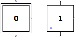
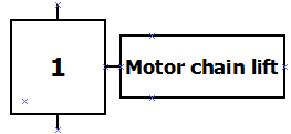
The step: each step has it's own number, placed in a square box. It's not required for all the steps to be ascending in value, but it does make it easier to follow.
The first step is marked by an extra square, and should be number zero.
http://www.sscoaster...tep_0_and_1.bmp
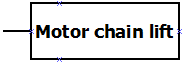
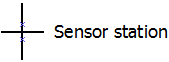
The action(s): during every step, one or several actions can be executed. These are placed in rectangular boxes and are connected with the step by a line.
http://www.sscoaster.../915/Action.bmp
http://www.sscoaster..._and_action.bmp
The transition: Between 2 steps, there's always a certain requisite that must be met. This is very similar as using the if function. The transition is not limited to one comparison, a whole formula can be used trough AND, OR and NOT.
http://www.sscoaster.../Transition.bmp
5.2.2. Rules of evolution
Serial connection:
Selection branch:
Parallel branch:
Jump:
Allowed, but better don't use this. (See pdf below.)
The rules of evolution are based on the description given by the following pdf. More information and examples can be found there as well:
Chapter 4 SFC
5.2.3. Closing the cycle
A SFC is a cyclic event. This means that it has to return from the final step to the initial step (0). There also has to be a transition between these two steps. (See serial connection.) On this line is often an arrow to point out the direction.
5.3. SFC: Examples
*some other day, I'm sorry*
5.4. SFC: With Arduino
5.4.1. Setting up the base code
There are different ways to program the SFC. So this is only one way to do this, variations or other methods are possible. However, this method doesn't really allow parallel branches.
First of all, you'll need to have an integer value to store the value of the active step. It should be zero by default. Also make long variables "previousMillis" and "TimeDifference" if you want to work with timed steps.
Secondly, there's the case method to program all the steps in. Using this, creating steps will be easy. The code, with one empty step is as follows:
5.4.2. Adding actions and transitions
Now, add the actions and the transitions. The actions are programmed in the corresponding case. The transitions are done by using the if function and are placed in the case from which the transitions leaves the active step.
Keep adding steps to complete the SFC you've drawn. At the end, jump back to step 0, and you're off!
NOTE: Normally, a certain action is only active if it's mentioned at a step. However, if you set an output true, and you jump to the next step, it will stay true.
So you either have to work with "SET" and "RESET" in your SFC. Meaning that an output is active when set, and remains active until reset in another step.
Or, you set all the outputs to false before you run the case. But then it's advised to use variables instead of writing the outputs directly. Because this would result in high frequent switching of the output. At the end of your program, you can write the status of the variables to the adequate output.
5.4.3. Timed steps
If a certain step has to be executed for a certain time, you'll need to know how long the active step has been running. For this, subtract the previousMillis from the millis(). But at each transition, the previousMillis will have to be set to the current millis.
Special thanks to Bart for his adaption to timing the steps.
5.1. Introduction
In sequential logic, the output of a logic circuit not only depends on the present input, but also on the history of the input.
A small example is detecting a rising edge. The output is high when the input is high now, but was low the previous cycle.
When you want to control your rides and coasters, a step-by-step controlling is mostly required. This can be achieved quite easily by using sequential controlling. To achieve this, a sequential function chart is the key. Using this, writing the program will be a lot easier.
5.2. SFC: Sequential Function Chart
SFC, or also "grafcet" in French, is a rule on how to draw your sequential control. It's mostly built using symbolic names instead of addresses so everyone has a the possibility to read it.
Basically, there are one ore several active steps, which will be executing a certain action. When a requisite is met, the next step will be turned active, deactivating the previous step.
Continue reading chapter 5.2 to learn how to draw your SFC.
5.2.1. Symbols
The step: each step has it's own number, placed in a square box. It's not required for all the steps to be ascending in value, but it does make it easier to follow.
The first step is marked by an extra square, and should be number zero.
http://www.sscoaster...tep_0_and_1.bmp
The action(s): during every step, one or several actions can be executed. These are placed in rectangular boxes and are connected with the step by a line.
http://www.sscoaster.../915/Action.bmp
http://www.sscoaster..._and_action.bmp
The transition: Between 2 steps, there's always a certain requisite that must be met. This is very similar as using the if function. The transition is not limited to one comparison, a whole formula can be used trough AND, OR and NOT.
http://www.sscoaster.../Transition.bmp
5.2.2. Rules of evolution
Serial connection:
- Two steps are are never connected directly and are always divided by a transition.
- Two transitions are never connected directly and are always divided by a step.
- The lower step will be active when the transition is true under an active step.
Selection branch:
- When 2 transition conditions are met after the active step, the leftmost step gets priority and will be active.
Parallel branch:
- All steps which are connected below this transition will be active if the condition is met. The active steps will be as many as the number of branches.
- If parallel branches are joined, the next step will be active when the last steps of each branch is active and the transition condition is met.
Jump:
Allowed, but better don't use this. (See pdf below.)
The rules of evolution are based on the description given by the following pdf. More information and examples can be found there as well:
Chapter 4 SFC
5.2.3. Closing the cycle
A SFC is a cyclic event. This means that it has to return from the final step to the initial step (0). There also has to be a transition between these two steps. (See serial connection.) On this line is often an arrow to point out the direction.
5.3. SFC: Examples
*some other day, I'm sorry*
5.4. SFC: With Arduino
5.4.1. Setting up the base code
There are different ways to program the SFC. So this is only one way to do this, variations or other methods are possible. However, this method doesn't really allow parallel branches.
First of all, you'll need to have an integer value to store the value of the active step. It should be zero by default. Also make long variables "previousMillis" and "TimeDifference" if you want to work with timed steps.
Secondly, there's the case method to program all the steps in. Using this, creating steps will be easy. The code, with one empty step is as follows:
switch(stepNumber) {

case 0:
;
break;
}
5.4.2. Adding actions and transitions
Now, add the actions and the transitions. The actions are programmed in the corresponding case. The transitions are done by using the if function and are placed in the case from which the transitions leaves the active step.
switch(stepNumber) {

case 0:

// actions step 0
MotorChainLift = true;

// transition to step 1 if the lift sensor is activated
if(sensorLift == true) { // requisite to be met
stepNumber = 1; // step to jump to
}

break;
}
Keep adding steps to complete the SFC you've drawn. At the end, jump back to step 0, and you're off!
NOTE: Normally, a certain action is only active if it's mentioned at a step. However, if you set an output true, and you jump to the next step, it will stay true.
So you either have to work with "SET" and "RESET" in your SFC. Meaning that an output is active when set, and remains active until reset in another step.
Or, you set all the outputs to false before you run the case. But then it's advised to use variables instead of writing the outputs directly. Because this would result in high frequent switching of the output. At the end of your program, you can write the status of the variables to the adequate output.
5.4.3. Timed steps
If a certain step has to be executed for a certain time, you'll need to know how long the active step has been running. For this, subtract the previousMillis from the millis(). But at each transition, the previousMillis will have to be set to the current millis.
TimeDifference = currentMillis - previousMillisStation;

switch(stepNumber) {

case 0:

// actions step 0
;

// transition to step 1
if(TimeDifference >= 2000) { // step time in milliseconds
stepNumber = 1; // step to jump to
previousMillisStation = millis(); // reset the timer
}

break;
}
Special thanks to Bart for his adaption to timing the steps.
![]()


