where does a 120v 15 amp car battery show up on your diagram? I see one 36-V battery hookup and a 5-V battery for the trigger circuit. Also, where can you find the iron cores and microswitches?
Linear Synchronous Motor (LSM) Launch
Started by
Tyrant
, Apr 25 2005 11:05 PM
113 replies to this topic
#62
 Launch: post #62")
Tyrant
-

-

- 2803 posts
Lead Engineer
Posted 22 January 2006 - 01:40 PM
We orginally were going to use batteries, but decided to use a wall socket power source anyways instead of having to constantly replace batteries. We blew about 4 different power supplies before settling on the car-battery-charger. The charger simply goes in place of the power-supply.
The microswitches I got at a local electronic surplus store called Gateway Electronics. As for the iron cores, I am not sure where you guys could get them, I had cut a bunch of them in the high-school's metals lab, since the teacher let me take a whole cord of metal flat-stock.
-Tyrant
The microswitches I got at a local electronic surplus store called Gateway Electronics. As for the iron cores, I am not sure where you guys could get them, I had cut a bunch of them in the high-school's metals lab, since the teacher let me take a whole cord of metal flat-stock.
-Tyrant

#63
CP-ephY
-

-
- 2751 posts
thumb abuser
Posted 22 January 2006 - 02:31 PM
So the charger connects to both the circuit with the electromagnets and the circuit that triggers the relay? and do the microswitches act like a reedswitch but just with lower sensitivity? Btw what have you got connected to the relay there in the second pic. Everything looks great so far. Nice work!!

#64
Tyrant
-
-
- 2803 posts
Lead Engineer
Posted 22 January 2006 - 03:19 PM
The charger power goes into the relays, there are 3 outputs and 3 inputs on the relay, one of the output/input pins is for the switch. The microswitches act the same as reed switches, they simply close the circut. The difference is that the microswitches are physical switches that need mechanical energy to close them (the train hitting them) while the reed switches are sensitive magnetic switches that uses magnetic force to close them. I am not sure what you are asking about with what is connected to the relays, if you are talking about the grey things, those are simply wire-nuts to help with wire management.
-Tyrant
-Tyrant
#65
CP-ephY
-
-
- 2751 posts
thumb abuser
Posted 22 January 2006 - 03:38 PM
the second set of wires that come out of the nut is connected to something with black tape over it. What provides the mechanical energy to close the micro switch? I see 4 input and output. Observe the circles I put. I see one input/output for the circuit hooked up to the microswitch (red circles). Then I see an input coming from the positive end of the battery and two corresponding outputs because of the switch inside the relay that alternates between circuits (blue circles). Then I see two inputs coming back in with another switch in the relay along with one output connecting to the negative end of the battery (green circles). Are you still using a 5VDC battery for the input/output for the microswitch circuit??
#66
Tyrant
-
-
- 2803 posts
Lead Engineer
Posted 22 January 2006 - 04:39 PM
Studying the circut more closely, we have made so many modifications to the original design plan that I wouldn't even really consider that a proper representation of it anymore. Soon I will, or either have Ron make up a new diagram with the most recent looking one. You can see in the picture attached that there are 6 pins, two sets are for the + - going one direction, the other for the + - going in another direction, and the other two pins are the + - outputs for the trigger circut. We had two relays, one controlling flow going on direction, another for flow going the other way. Sorry if this is hard to understand, its a rather complicated process that is tough to explain online simply with words and pictures.
Plus engineers suck at the english language.
-Tyrant
Plus engineers suck at the english language.
-Tyrant
#67
CP-ephY
-
-
- 2751 posts
thumb abuser
Posted 22 January 2006 - 04:47 PM
It's just hard to understand when the design plan keeps changing lol. So you have wires connecting to all the pins right?
#68
Tyrant
-
-
- 2803 posts
Lead Engineer
Posted 22 January 2006 - 05:14 PM
Actually, if you look at the first set of pictures I posted a couple days ago, you will notice that two pins aren't being used.
-Tyrant
-Tyrant
#69
CP-ephY
-
-
- 2751 posts
thumb abuser
Posted 22 January 2006 - 06:27 PM
Wow I am so confused. From the diagram you showed, all 8 are connected. Just take a look at the post where I circled everything. There appears to be eight places where the wires come in and out. When can you post a new circuit diagram? I am looking forward to seeing the final layout of everything.
#70
Tyrant
-
-
- 2803 posts
Lead Engineer
Posted 23 August 2006 - 11:58 PM
A CPU controlled relay board has been hooked up. A program has been written. Calibration is currently being worked on.
*EDIT* And this thing has major potential now.
*Double EDIT* Here are some photos of the devolpment we are doing. I pretty much take video of the original pulse, then go into Adobe Premier Pro, count the number of frames it takes for the car to make it into the next section, divide that by 30fps, then multiply times 1000 to get the approximate milliseconds to plug into the program. Ron enters the numbers, as well as wrote the program on his own. We get some approx numbers, plug em in, and tweak tweak tweak.
http://img206.images...3/dev003cc9.jpg
http://img219.images...4/dev010te6.jpg
http://img208.images...4/dev007by6.jpg
http://img219.images...8/dev002xp7.jpg
-Tyrant
Mod's have to follow rules too-CC10
#71
Tyrant
-
-
- 2803 posts
Lead Engineer
Posted 24 August 2006 - 01:24 AM
Screw a triple edit.
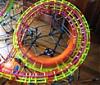
Here is a demonstration of how the process goes. I insert numbers, watch it launch, tweak the numbers, and keep going and going till it works flawlessly. Right now it won't seem like much speed, but that is because we only have one accelerating magnet on the track as of now. The first magnet is merely a "push" magnet that doesn't act as an accelerator.
We will be adding on at least two more magnets tomorrow afternoon/night then tweaking the program even more, hopefully get some more solid numbers so that I can try and derive a formula that will allow to adjust the entire set of magnets on the fly.
Currently the first "push" magnet is on for 265 milliseconds, then a "dead-time" where nothing is turned on for 65 milliseconds, then the first accelerating magnet is set for 150-ish milliseconds (+ or - 10 milliseconds). The reason the 2nd magnet isn't a solid value is because we need to test and see if the 3rd magnet will affect the 2nd magnet and its force in any way. For example, when firing only the first magnet, I thought I had come up with a solid number of 310 milliseconds, however when factoring in the 2nd magnet, the number got dropped to 265 as the most effective.
Anyways, here is the demonstration video:
http://media.putfile...M-Demonstration
Also, always remeber the horrors of Judy Blume:
http://media.putfile...bout-Judy-Blume
Enjoy. The next couple of days should be very interesting as far as progress comes along.
-Tyrant
#72
coastergeekrtc
-

-
- 2653 posts
A God Among Users
Posted 24 August 2006 - 01:50 AM
Sweet dude. I see you're using the PC Relay Controller...I was looking into using it to control my Halloween haunt. Nice to see you're still working on this.
*Insert signature here*
#73
RonStoppable102
-

-

- 39 posts
Master of Hotglue
Posted 24 August 2006 - 08:42 AM
Heh, sweet, if you ever pick it up, let me know.
The instructions that come with it, espically on how to program it, are very vague, so I had to do alot of diging myself. Once I get a nice program written, I'd be glad to give you the source and/or the exe's.
It's nice to actually apply the yearlong C++ class I took, but I'm having trouble remembering it all. If you guys ever have the chance to take a programing class, espically C++, I suggest you take advantage of that.
Oh, and as for this step up, It amazes me what amount of control we now have over the car, and what a big difference a 15ms change can make. Looking back, it would've been impossible to even get lucky without having some sort of "PLC" like the real LIM/LSM launch coasters. Live and Learn!
University of Missouri - Rolla
Computer Engineering
#74
smallish
-

-
- 614 posts
Entry Engineer
Posted 24 August 2006 - 12:48 PM
Yes! This is back and better than ever!
Although it doesn't look any easier...
Once you master it it would be nice to see an impulse coaster, becasue it's almost impossible to make a working one any other way (without using two tracks like Vertigo).
Although it doesn't look any easier...
Once you master it it would be nice to see an impulse coaster, becasue it's almost impossible to make a working one any other way (without using two tracks like Vertigo).

#75
coastercrazy10
-

-
- 7008 posts
Mad Scientist
Posted 24 August 2006 - 03:35 PM
I can see the potential. If you guys continue this, this will be the most innovative thing done with knex since...well, ever!
-CC10
-CC10
SSCoasters Staff | The SSCoasters Forum Rules
University of Illinois at Urbana Champaign | Computer Science & Mathematics
Fireball | Kingda Ka | Inclination | Diamondback
#76
zapa
-
-
- 682 posts
awsome member
Posted 24 August 2006 - 04:12 PM
Yes, this has alot of potential. With the right program, you could probably make the car come to a complete stop for how ever long you wanted, and then launch it.

^My second model^
#77
Tyrant
-
-
- 2803 posts
Lead Engineer
Posted 24 August 2006 - 04:40 PM
Actually, one idea I had thought of to make the car stop on the same point everytime before launching was to have a magnet holding the car in position (the magnet would be on the side of the car, rather than underneath) and would turn off once the circut started firing off magnets.
-Tyrant
-Tyrant
#78
Tyrant
-
-
- 2803 posts
Lead Engineer
Posted 28 August 2006 - 01:39 AM
UPDATE. Finally starting to get some better timing numbers, still trying to work out an equation which works well in prediciting the next set of values.
-Tyrant
-Tyrant
#79
jumpboy
-
-
- 1428 posts
Not-So-Senior Member
Posted 01 September 2006 - 12:22 PM
Well, I am still wrapping the cores, up to about 5 of them done by now. They each take about 45 minutes to wrap neatly and tightly. Tightly wrapped is how they need to be done, since any air-gaps will slightly reduce the magnetic field created by the wire. A few are fine, and sort of expected since its hard to get them to be perfect. Anyways, I am still in the process of designing the placement of the electromagnets and the switches, as well as creating an AutoCAD layout of where I need to drill holes for wires and clean cable management. Although I don't have any pictures of the actual launch yet, I thought I would show you pictures of the various components of the launch itself. To start you off, this is a picture of one of the compleleted electromagnets, notice how the wires are tightly wrapped, the tape on the ends is to keep the wires from jumping off and causing a mess. Also the other picture shows a magnet about half-way through completion.
Completed Electromagnet
Half-way completed Electromagnet
The other big thing that most of you seem to be getting confused on is the Magnetic Switch. I was originally going to be using switches from Radio Shack, however the price was rather steep with them being around $5.59 each. So I went down to Gateway Electronics, a surplus electronics store native to St. Louis and was able to find some older magnetic switches that were only $1.95 each, and bought 10 of them. I also bought eight 9-Volt batteries from Kmart for $18. The 9-Volt batteries are the main power supply, 4 for each group, totalling about 36-Volts going across the electromagnets at once.
Magnetic Switch
9-Volt Power source
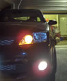
Now moving onto the car. Right now for testing purposes, I am just using one car that has an aluminum plate mounted underneath the chassis which I custom-built from a piece of $3.95 Aluminum Duct casing. The Aluminum plate was used to hold the 3 magnets close to the electromagnets during the launch (about 0.125" above them), Aluminum was used because it doesn't not have any magnetism, thus will not interfere with the magnetic field. The 3 magnets that are mounted on the train are 1/2" round button magnets from Radio Shack, they can be bought in a pack of five for about $1.95. I mounted the magnets so only the southern pole is facing down. Mounting was rather easy, as I just used a hot-glue gun to put the magnets to the aluminum, and then to attach the aluminum plate to the car.
A view of the Aluminium mounting bracket
A close-up view of the 3 magnets mounted inside
I also managed to create an AutoCAD wiring diagram to help me in the logic of wiring up the entire launch. Some of you who may know some stuff about electrical circuts will be able to decipher the diagram. Quite simply, the labels MS# represents the Magnetic Switches, while the SOL# represents the electromagnets. The switches are mounted in a 1-2-3-4-5-6-7-8-9-10 fashion, right above the electromagnets. Take notice at the battery source. Notice the top ladder uses a source in which the current moves + to - and the lower ladder uses a source in which the current moves - to +. When the train hits one switch, it closes the circut for whichever switch it is on, and sends the current moving throughout, depending on which way the current moves, the electromagnets will have a different polarity. So if the train is currently in switch #3, the current will be flowing from + to -, so the polarity on the electromagnets will change such that it will push the train into the next switch. Power is then cut, and the next switch (#4) is activated, which reverses the current flow, reversing the polarity, and once again pushing the car into the next switch. Hopefully this diagram will clear up some confusion.
Electrical Wiring diagram
-Tyrant
Could you repost these? I'm looking at trying something like this for science fair.
University of Maryland 2011
#80
poizone
-

-
- 995 posts
Small Spaces
Posted 01 September 2006 - 02:14 PM
*GASP* Its Another Back From the Dead!!!
Currently compiling a massive list


