I've always wanted to make or at least see an LED Cube. I hope you can do it!
Thanks! I'll make sure to give you guys some pictures and videos when it is done!
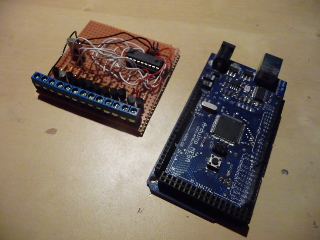
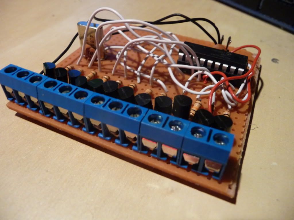
I just can't see what is that green thing used for.
But I read you can program it, so I became interested, because I like programming
( language basic untill now).
So what is a PIC programmer?
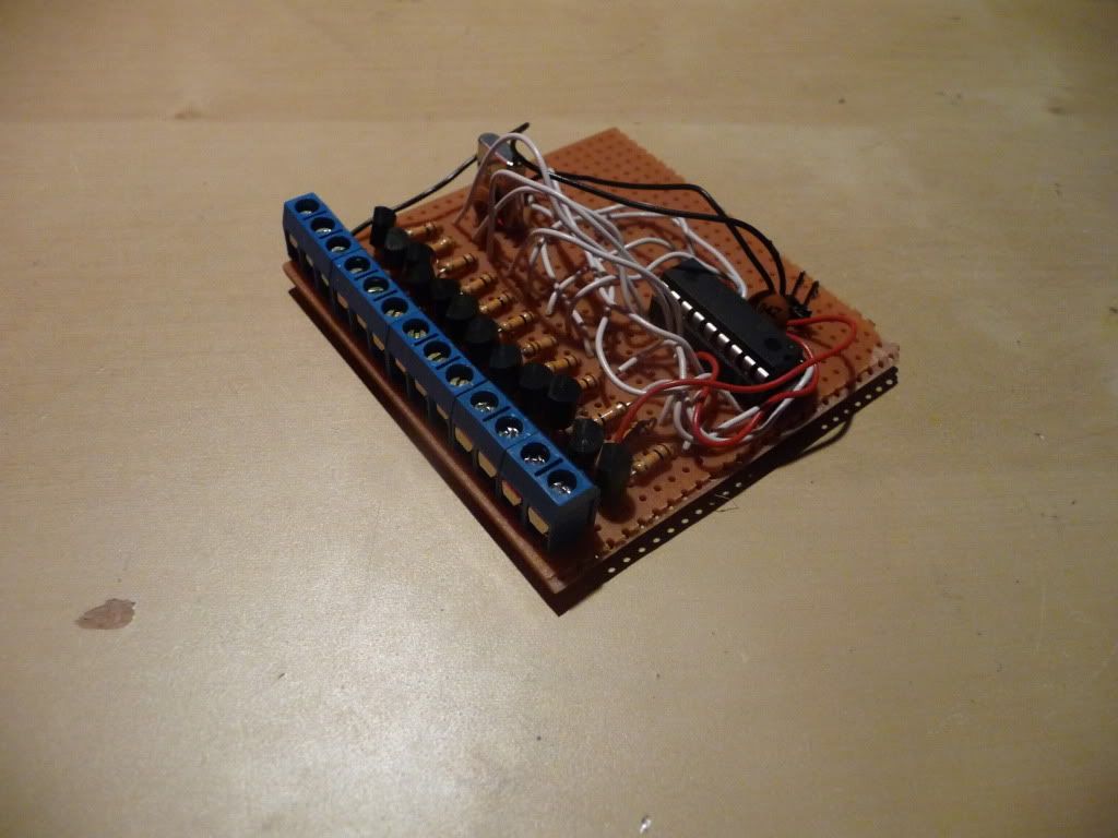
Haha, you were wrong there. The "green thing" aka a circuitboard, is there only to program a chip, which you can then take out and put it in a machine or a something. An arduino is practically just a chip with some easy connectors on it.
Another thing:
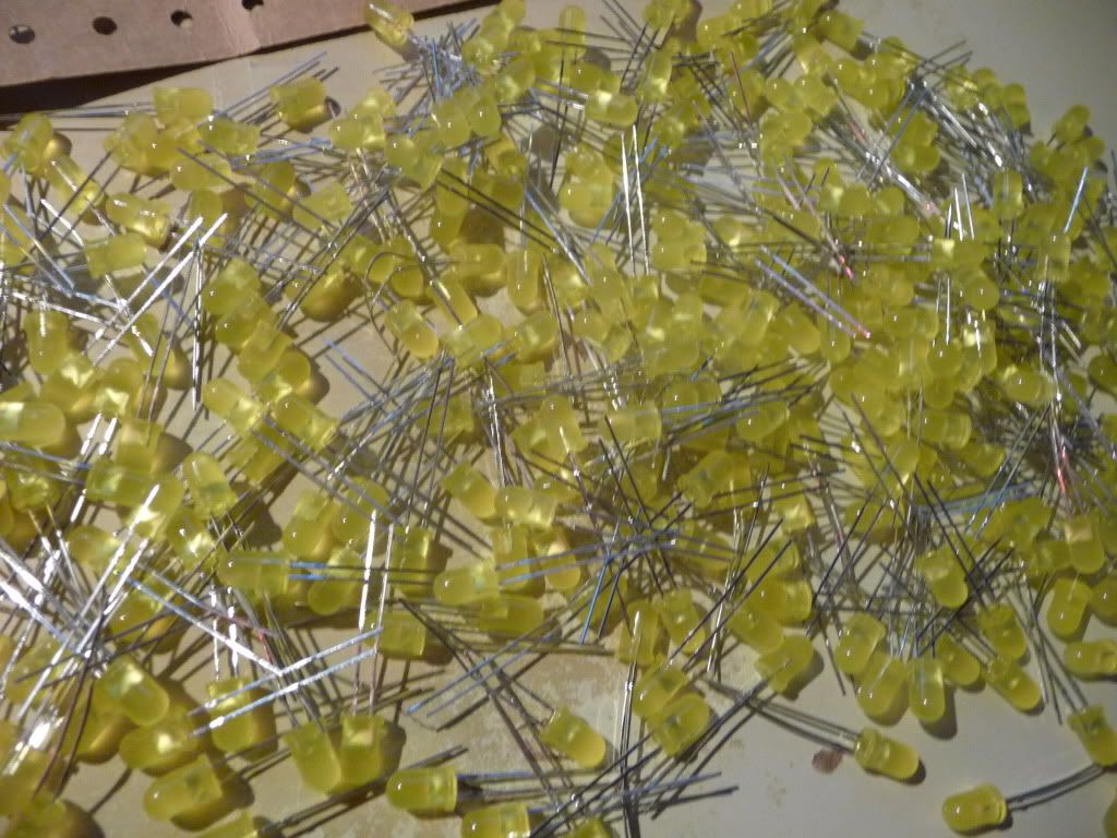
For the ledcube, I am still trying to figure out what the right size is.
I bought 300 leds, so the maximal size I can build is 6x6x6 leds.
As for the pins: I have some inventive way of using the electronics which allows me to use only a small amount of pins for a lot of leds. I have to use multiplexing in my code for that.
The formula for how many pins I need is the following:
pins = width(in leds) * dimensions.
since it is a cube, it has 3 dimensions, which leads to:
4x4x4 cube: 12 pins
5x5x5 cube: 15 pins
6x6x6 cube: 18 pins
There are some ways to save even more pins, which can be done from 6+ leds width.
That way I can save 3 more pins on the 6x6x6 cube. This does make the electronics a lot harder.
The chip I will be using has only 16 output pins, so I think the 6x6x6 cube is something I should rather not try.
But I don't know whether I'll build a 5x5x5 cube or a 4x4x4 cube.
A 4xcube saves me half of the leds, but with a 5x5x5 you can make much cooler movements.
Also, a 5x5x5 cube has a center-led, which also allows cooler movements.
But the programming on a 5x5x5 cube will be much harder.
So yeah, what should I do? Should I use the remaining 3 weeks it takes for the parts to ship to program an awesome code for the 5x5x5 cube, or should I take the easy way?
Edit: Oh, and 1 more thing: Never start using PIC programmers unless you are willing to spend days and days of googling and finding out how to get it working. It is really a lot of work, and therefor I recommend arduino to all of you, arduino is open source and there are way more tutorials online.
-Suck.