Jump to content


FTGU Electronics stuff (Reflective Infrared Sensors)

insanity looper

  • Please log in to reply
7 replies to this topic

#1 ForgotToGrowUp

ForgotToGrowUp

    Lead Engineer

  • 1732 posts

Posted 19 September 2012 - 09:32 PM

Hey everyone. Like everything else I make very slow progress with this electronics stuff. Lack of personal time and long lead times buying things cheaply. It's been fun, re-learning things I did decades ago... at one time I got an electrical engineering degree, then was a software engineer for over 20 years and now am just doing engineering management (i.e. rotting my brain) so this has really been fun stuff.

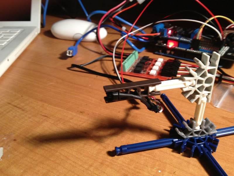
Here is what I have to play with so far. I think this is going to get me far. It is not the cheapest way to go but I prefer to not solder things if possible and want to be able to prototype and reconfigure things easily.

I got this Arduino Mega compatible board on eBay for $20. Nicely made and seems to work perfectly.

Posted Image

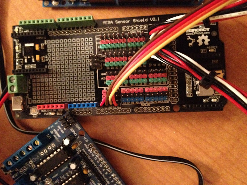
I bought a prototyping shield with the mega but didn't like that because it either meant soldering or using a breadboard. I looked around and found several interface or sensor shields for the Mega. After looking at them all I decided to go with this one from DFRobot. It is expensive at $20 (same price as the Mega!) but really nice because the layout allows you to put standard Arduino shields on top of it with straight pass through of the standard pins on stacking headers. It has all the other digital and analog pins grouped in rows of three with a ground and +5v pin. This is really convenient to plug in other stuff. You can use ribbon cable or servo cables. I found servo cables at arduino-direct real cheap. It also has 3 Xbee slots, and SD card slot, which will be nice as I get more adventurous with this. You can use an external +5V for the peripheral pins, which lightens the load on the Mega. I really like this shield! (if you go to buy it make sure you get v2.1, much nicer than previous models)

Posted Image

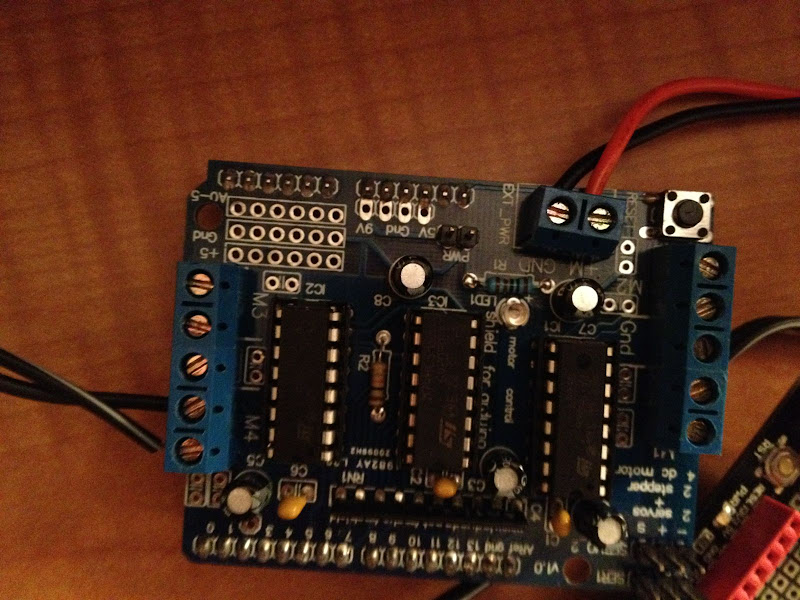
This motor shield is a knock off of the Adafruit shield. Very nice with 2 L293D H bridge chips. I've played with this a bit to power Knex motors.

Posted Image

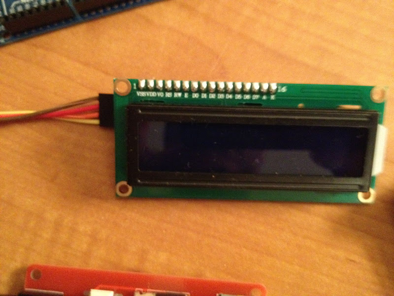
This little display was only $12 and it works off the IC2 or Serial lines on the Mega.

Posted Image

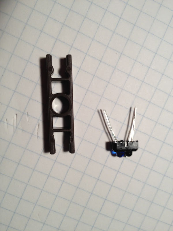
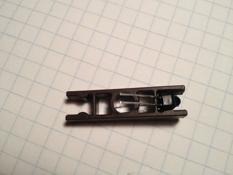
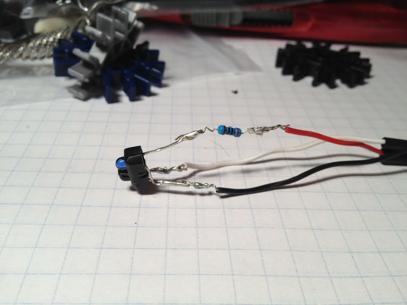
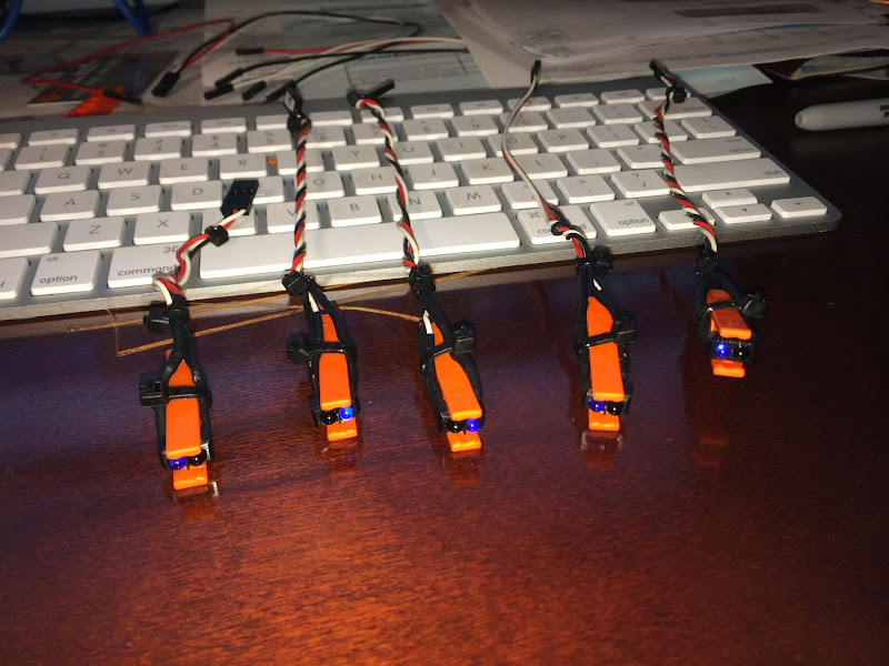
Cheap simple buttons but set up for the 3 pin cables, couldn't be easier!

Posted Image

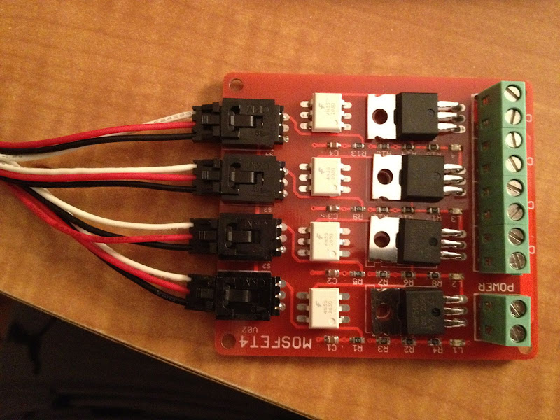
Since the motor shield can only drive 4 DC motors and is not stackable I was looking for other ways to do it. This board from arduino-direct has 4 MOSFETs optically coupled to the interface. Like the motor shield you provide separate power to the motors from an external source. I think this is a great way to go. I plan on using this board to power the motors for my lift and use the other shield for the brake runs and station. This is the only thing I have not tested yet.

Posted Image

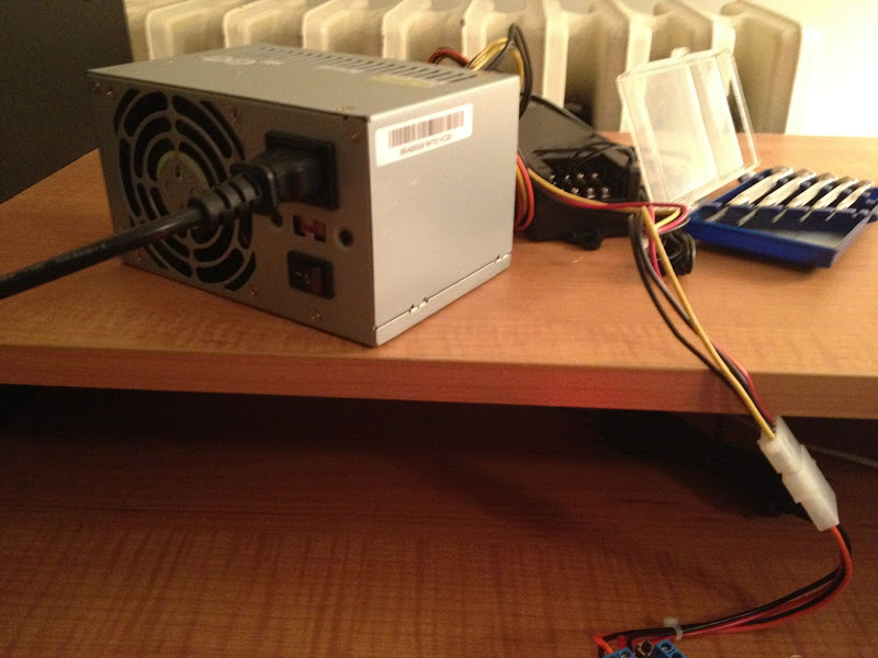
got this ATX PSU on eBay for $0.99!!! ($5 shipping) I cuta disk drive extension cord so I could easily plug my expansion boards into this. I am going to also splice in a female USB plug (without tX, rX pins) so I can power the Mega from it when not plugged in to the computer. (read this is the safest way to do it so you do not accidentally power it from an external supply while plugged into a real USB and it does not bypass the fuse that is between the USB plug and the Vin pin.)

Posted Image

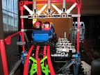
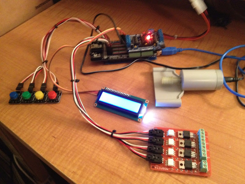
Here is the whole set up.

Posted Image

even found a use for this old macbook that isn't good for much else at this point.

Posted Image

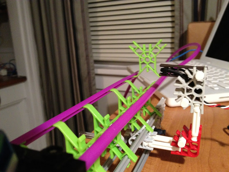
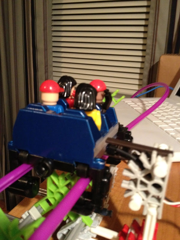
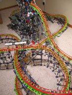
Now I just need to get back to building my coaster!!!

Comet Recreation still underway.

Proof you never grow up if you keep playing with toys!


#2 Jogumpie

Jogumpie

    Living through the great Gump hiatus...

  • 13586 posts

Posted 20 September 2012 - 06:30 AM

Looking forward to this, Jeff. :)


SSCoasters Administrator
The SSCoasters Forum Rules
DD_signature.jpg
YoutubeButton.pngFacebookButton.png


#3 ForgotToGrowUp

ForgotToGrowUp

    Lead Engineer

  • 1732 posts

Posted 21 September 2012 - 09:48 PM

Thanks Gump.

FYI I've tested that MOSFET board and compared it to the L293 shield. Driving the motors through the MOSFET transistors is considerably more powerful than through the H Bridge chips even when PWM is set to 255. With both boards getting 12.6 volts in, the H Bridge board is only putting out 11.5 with PWM set to 255. The MOSFETs have no measurable voltage drop.

There is no reason PWM wouldn't work with the transistors for speed control, the only draw back to them is they can not be reversed like the H Bridges. I am definitely going to use the MOSFETs for the lift motors with not modulation. Just on and off.

Comet Recreation still underway.

Proof you never grow up if you keep playing with toys!


#4 sunnysideup

sunnysideup

    Newbie

  • Pip
  • 1 posts

Posted 01 October 2012 - 02:09 PM

get a breadboard for easy prototyping and it can be useful for junctions without soldering


#5 ForgotToGrowUp

ForgotToGrowUp

    Lead Engineer

  • 1732 posts

Posted 01 October 2012 - 10:15 PM

^Thanks I do have a breadboard and I did use it to test this quickly. :-)

I was looking for alternatives to reed switches for sensing the trains. Nothing against reeds they work great, although they are a little pricey. I looked into optical sensors and found these to be incredibly cheap.

TCRT 5000 Infrared Reflective Sensor

You can find these all over eBay at 10 for 2$ + free shipping from China. I got them in a week.

Posted Image

It's an infrared LED and a phototransistor packaged together. It works using reflection of the infrared light. I found it works from about an inch in normal light with most objects that are not completely black. You do have to be thoughtful of ambient light and heat sources though. The higher the ambient light the more sensitive it is. I found a hot desk light pointed at it would set it off non stop from about 3 feet away. Most black things will not work unless they are very shiny.

They fit nicely in any Knex connector if you cut off the little bumps on the inside of the connector as I have with this ladder.

Posted Image

Posted Image

Like any other LED be sure to put a resistor in series with the infrared LED. I put it on the anode side and connected to +5V, I connected the collector of the phototransistor up to an INPUT pin on the arduino set to high, using the internal PULLUP resistor. I bent the cathode of LED to connect it with the emitter of the transitor and connected both to the ground lead.

(resulting in a circuit similar to this)

Posted Image

Posted Image

After it was soldered I put heatshrink tubing over the leads and just pushed it into the ladder connector.

Posted Image

This simple connection is just one of the many ways you could position it on the track. I was able to ideally position it so it is just a mm or so from the car's silver stripe.

Posted Image

Posted Image
This is sturdy enough from keeping it from getting damaged in accidents.

Posted Image

Here is a test video. You can see the LED on the MOSFET board light up and hear the motor turn on and off.


edit:

I also had a test video of a motor being driven by the pre-made Motor Shield. Just a test sketch to show the motor speeding up slowing down and changing direction.


Comet Recreation still underway.

Proof you never grow up if you keep playing with toys!


#6 iCoaster44

iCoaster44

    French K'nexpert

  • 383 posts

Posted 11 October 2012 - 11:51 AM

^ A question
Why you don't put the sensor on the middle of the track like Jogumpie ?


#7 ForgotToGrowUp

ForgotToGrowUp

    Lead Engineer

  • 1732 posts

Posted 11 October 2012 - 12:10 PM

Keep in mind, Gumps sensors are magnetic and these are using reflected infrared light . I could mount them under the track pointing up and because I have pennies glued in all my trains it would work fine. However I think I might get more false reads pointing up as there is greater potential for light from a window to hit it etc.

I also like the way they look on the side of the track! Plus these will be used mostly in places where I have chains and/or brakes so it is probably going to be easier to mount on the side.

Bottom line is you can mount them any way you want as long as something reflective passes within 1/2" or so.

Comet Recreation still underway.

Proof you never grow up if you keep playing with toys!


#8 ForgotToGrowUp

ForgotToGrowUp

    Lead Engineer

  • 1732 posts

Posted 11 December 2013 - 09:03 PM

Posted Image

I finally got around to making some more sensor devices out of those TCRT 5000 parts. Pretty simple but since I am over zealous with the soldering iron and have poor eyesight and clumsy hands I ended up only getting 5 working parts out of 5 TCRTs. Good thing they are so ridiculously cheap! I only needed 4 so I am good to go!

My original tests were very susceptible to false readings due to ambient light or heat sources. I was using them as digital inputs. found a great idea to use them as analog inputs and alternate the firing of the infrared LED and compare values. This completely eliminates the false readings. The devices work even in the presence of a strong ambient heat/light source as long as the object to be detected blocks the ambient source from view.

Here is the little test sketch
// read data from an infrared sensor 
// and output the values on the serial port once a second

const int statusLED = 24;   // digital out which indicates object presence
const int irLED = 20;       // digital out which powers the ir LED
const int irDetector = A15; // analog input which measures the ir signal
const int trigger = 100;   // difference between ir values with led on and 
                           // off which triggers object presence status

int values[2];             // signal with ir-LED off and ir-LED on.
boolean object = false;    // object detected?

void setup() 
{                
  // digital pin used for status (on: object, off: no object)
  pinMode(statusLED, OUTPUT);
  digitalWrite(statusLED, LOW);    
  // digital pin which controls the infrared LED
  pinMode(irLED, OUTPUT);
  digitalWrite(irLED, LOW);    
  
 pinMode(irDetector, INPUT);
 digitalWrite(irDetector, HIGH); //use internal pull up resistor.
 
  // enable serial output
  Serial.begin(9600);
  Serial.println("Arduino started...");
}

//
// print the number of the counter cycle and the values, 
// but at most once a second.
//
void printValues()
{
  static int ticks = 0;
  static int counter = 0;
  counter++;
  int temp = millis();
  if( ticks + 1000 <= temp )
  {
    ticks = temp;
    Serial.print("[Cycle ");
    Serial.print(counter);
    Serial.print("] off:");
    Serial.print(values[0]);
    Serial.print(" on:");
    Serial.print(values[1]);
    if( object )
    {
      Serial.println(" Object detected!");
    }
    else
    {
      Serial.println(" Clear skies...");
    }
  }
}

void readValues()
{
  values[0] = analogRead(irDetector);
  digitalWrite(irLED, HIGH);    
  values[1] = analogRead(irDetector);
  digitalWrite(irLED, LOW);
  object = (values[0] - values[1] >= trigger);
  digitalWrite(statusLED, object);    
}

void loop() 
{
  readValues();
  printValues();
  delay(25); 
}


Comet Recreation still underway.

Proof you never grow up if you keep playing with toys!


Also tagged with one or more of these keywords: insanity, looper