 image.jpg 116.44KB
0 downloads
image.jpg 116.44KB
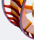
0 downloadsToday I will be showing you how to make this thing. It is a pop-up brake system for VV track. Due to its modularity, it can be built in a wide range of lengths, limited only by your piece collection. There is no piece count so just read through the tutorial before building.
The brakes use HTT tubing clipped onto several cylindrical assemblies. When these cylinders rise, the tubing is positioned to rub against the bottom of the train cars above it, slowing them through friction. When the pistons are lowered, the train is once again able to move freely. Due to the lack of a drive system the brake assembly will need to be attached to your model at a slight downward slope so that the train rolls forward under gravity when released from the brakes.
D8EE0218-46A1-45FB-B35E-C0DCBEFEC0A9.jpeg 109.87KB
0 downloads
C90E1801-0465-4D57-97C4-5A435402C94E.jpeg 97.43KB
0 downloadsThe brakes in their lowered and raised positions.
57CABDB3-2ACF-4394-8E88-30191CD373C2.jpeg 90.85KB
0 downloads
6ADD64FC-0120-4355-9AD0-6FA7CF8CA5E0.jpeg 79.72KB
0 downloadsSome pictures with a car on the track to show clearances.
And now, the tutorial:
E61F41A6-9572-4FE9-A127-0C17FE24D7A6.jpeg 109.89KB
0 downloadsFirst, start by constructing this assembly. You can build it as long as you like, just use ladder connectors to connect several rods together. Place the U-shaped red-connector-and-blue-rod assemblies at regular intervals along the rods, probably a bit closer than I have here. Since I am only building this to be one grey rod long, I am only using two of these.
F8DBB56F-796F-4840-9B8D-DC105BF28397.jpeg 88.62KB
0 downloadsPut these pieces and spacers in each open blue rod on each U-shaped piece.
147D2838-04C9-42F4-8E0D-8957508E2146.jpeg 113.66KB
0 downloadsNow add these two-way connectors to the top of the blue rods and clip rods along the length of your brake run. There should be ‘wiggle room’ on the blue rods equal to two blue spacers, allowing the one-way connectors and spacers to move up and down.
9F149F0F-8339-4F26-9201-4C4AE142AB7C.jpeg 91.36KB
0 downloadsNext, make several of these assemblies and attach them along your brake run, spaced like so:
D008DDAF-C7B5-4794-8321-D798D92EC73F.jpeg 115.68KB
0 downloadsThe red connectors should line up with the cross ties on a section of VV track. Obviously, a longer brake run would require more of these assemblies along its length.
D0482E51-5B40-426B-A884-073E349A37E3.jpeg 113.17KB
0 downloadsAdd these yellow connectors along your track. Face them all in the same direction to ensure there is enough space between each connector for the cylinders.
7473948C-36FB-406B-968A-6D77B9FDF170.jpeg 114.05KB
0 downloads…and attach it to your frame, like so.
The structural portion of the brake run is finished. Now on to the mechanism.
D9B2A742-8B2B-4899-9B8B-C3D704034AE8.jpeg 123.71KB
0 downloadsNow build this piece. Connect enough rods together to equal the length of your brake run and attach five-ways along the rod corresponding to the U-shaped assemblies along the frame. Each five-way will connect to the green rods on the one-way connectors on the blue rods of the frame, so space them accordingly.
E30A2102-A2A9-4665-A084-BB538F099790.jpeg 121.14KB
0 downloadsNow, add Y-clips along the rod(s), spaced between the cross ties of the track, like so:
C96576B2-829B-46F2-898C-12BC061F41BE.jpeg 96.56KB
0 downloadsThese Y-clips will hold the cylinders which support the tubing on top of the track.
B2DA1FC9-6D6E-45F4-9138-6B8F44D71AC1.jpeg 111.4KB
0 downloadsPlace one micro snowflake with a standard hole on the last Y-clip, the one that the train encounters last, at the end of your brake run.
9CA1B90E-2775-4C58-A183-D02E3DDF8D90.jpeg 68.26KB
0 downloadsClip one yellow rod on the snowflake, like so. You can use silver (1 1/2 units) or blue (2 units) spacers here. I only used silver spacers out of a lack of blue spacers.
0B78F5C1-81A7-4BA1-A729-F9DCC7D028F4.jpeg 110.2KB
0 downloadsSnap a connector onto the bottom of the yellow rod, sandwiching the standard rod between the snowflake on the Y-clip and the bottom connector. You can use an eight-way or a seven-way 3D connector here.
7738F32D-128E-4CD5-9AD1-4A138052F649.jpeg 70.93KB
0 downloadsAttach three more yellow rods with spacers to the connectors, like so. The entire assembly should be sandwiched to the standard rod with virtually no wiggle room.
E7BD5560-0566-467F-A080-F327E904C4A0.jpeg 110.77KB
0 downloadsAdd these two ladder connectors to the yellow rods.
16149968-A271-4B2D-9DB1-77C3AD74FC88.jpeg 98.33KB
0 downloadsBuild this thing…
1025B782-EEA7-4286-BC90-A3793E3E7254.jpeg 100KB
0 downloads…and slide the black rods into the holes of the ladder connectors. This piece will keep the ladder connectors aligned left-to-right.
48DFFA32-B31B-49A4-9041-151581AEDAEE.jpeg 99.44KB
0 downloadsAdd ladder connectors to the remaining two yellow rods.
A93DE917-215D-4C6C-9A24-C5954844250F.jpeg 105.79KB
0 downloadsNow add yellow rods to each ladder connector.
You have now finished a single cylinder. Repeat the last few steps to add cylinders to all but the first Y-clip.
B92AB407-D727-48A6-9279-B50F07FACDE5.jpeg 123.83KB
2 downloadsThe first cylinder will be constructed slightly differently to allow for a smooth entry into the brakes.
AB5BFF83-AE4C-4C59-A742-3F8C6CE6599A.jpeg 117.86KB
0 downloadsStart with two yellow rods with spacers and a lower connector, like before. Make sure the yellow rods are on the side closest to the other cylinders.
FC53CAD5-5702-46C1-904F-ADFC090EC692.jpeg 118.4KB
0 downloadsNow add a red rod and spacer on the other side of the connectors.
2F32023B-C1C5-424C-921D-C565BFC5F7D2.jpeg 102.47KB
0 downloadsNow add a three-way connector and another red rod onto the assembly, like so.
5C4CB57F-5C05-4E5F-9879-E2FF2CBBAFBB.jpeg 120.77KB
0 downloadsFinish off the yellow rods with a ladder connector and another yellow rod.
You are now finished with the cylinders portion.
7362976C-C22E-45AB-B754-F315C765B73C.jpeg 119.37KB
0 downloadsConnect the five-ways to the one way connectors and green rods of the structural portion, like so. You will need to temporarily remove the blue rods on the bottom of the structure to fit the cylinders portion through.
261AA61A-39F5-4BA4-9B48-230FD95F2BD7.jpeg 117.68KB
0 downloadsEnsure that all cylinders fit properly in the gaps between the cross ties. You may need to shift some of the cylinders around.
17378792-AF7F-4281-A62A-72D09B936937.jpeg 110.58KB
0 downloadsNext, temporarily clip connectors below the one-way connectors attaching the five-ways to the frame. Any connector or clip will do here, it is only temporary to assist in adding the tubing.
5E90F9C3-5072-4452-9247-F63ADE7CE49F.jpeg 120.51KB
0 downloadsAttach the tubing to the tops of the micro rods, like so. I recommend that you start from the beginning of the brake run, at the red rods. You will need to space the yellow and red rods on the first cylinder apart, like so:
74CF65D1-818D-47C9-A8AA-7CBCFA86F0D1.jpeg 85.15KB
0 downloadsIf these are not spaced apart, the rigidity of the tubing will be enough to occasionally disconnect itself from the red rods.
E513BAD3-50F1-450F-9792-2D7B9AFE982E.jpeg 102.38KB
1 downloadsEnsure that the tubing at the beginning of the brake run does not overlap the cross ties. You can now cut the tubing. Finally, remove the temporary connectors that you added earlier to the blue rods. You are now done with the brakes!
How you raise/lower the brakes is up to you. I can imagine several possibilities, ranging from solenoids to scissor lifts to a crankshaft-and-piston assembly. Remember to construct your brake run at a slight downgrade to allow the train to roll forward when it is released from the brakes.
Thank you for reading through my tutorial, and good luck with your coasters!
Sorry for sideways pictures, I have no control over it on my phone. At some point on my computer I might try to come back and fix these.