#1
Posted 21 December 2018 - 01:49 PM
About 4 months ago I started designing this ride vehicle. It's a tracked motion base vehicle with 4 degrees of freedom, just like on Spiderman or Transformers at Universal.
20181220_075805.jpg 106.18KB 0 downloads
20181220_075757.jpg 95.72KB 0 downloads
20181008_080726.jpg 106.91KB 0 downloads
It doesn't have wheels, so its only motions are: 3 crank arms up/down, yaw, lap bars open/close, and some RGB LEDs.
All the pieces are custom-designed in SolidWorks and 3D printed on my machine. To control it, I'm using an Arduino Nano and some hobby servos.
The motion profile is "randomized". Each motor has 3 pre-programmed profiles that are chosen at random, so there are a total of 3^4=81 unique motion profiles. I'll need to add more yaw motor profiles, because as you see in the video, it's pretty obvious if you get the same yaw profile 2 times in a row.
I designed a custom PCB (with lots of help from my coworkers) that acts as a slip ring and had it manufactured. It's attached underneath the yaw ring, and has circular traces that touch spring-loaded contacts in the motion base. The slip ring allows me to transfer 5V, Ground, and digital signals into the cabin while it's rotating. It also has a trace that is connected to 5V on one half of the ring and Ground on the other half. This acts like an index, which allows me to home the yaw axis and make sure the cabin is facing forward after each run.
The rear seat has a cavity inside it that holds a micro servo motor, which I'll use to open and close the lap bars. I can't control this servo through the slip ring because that would have added too much noise and I'd have a twitchy motor. So there will be a second Arduino Nano inside the rear seat, which I'll use to control the lap bar servo and cabin LEDs.
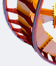
The next thing on my list is to finish the front of the cabin, and add LEDs to the jet engines. The jet engine spirals are white and hollow, so the light will shine through from the LED inside. The LEDs are NeoPixels, so I can do any sort of color patterns I want!
20181101_185314.jpg 59.04KB 0 downloads
#2
Posted 22 December 2018 - 04:55 AM
That looks very interesting, maybe try to use an algorithm to send to servo's the desired position? Or would that be tot hard.
#3
Posted 22 December 2018 - 01:07 PM
Very impressive indeed. How many attempts did it take to get a working 3D design? I'm assuming it couldn't possibly be the first try!
NeoPixels are awesome! Did you use through-hole or surface mounts? I worked on a couple projects using NeoPixels and DotStars, they are absolutely brilliant. Crazy how small the chip inside the LEDs are.
Keep up the work. Subscribed
[SIGPIC][/SIGPIC]
Pigs are better when green.
#4
Posted 22 December 2018 - 06:30 PM
Nice! You got it working! Can't wait to see the lap bars and the lights going!
#5
Posted 26 December 2018 - 05:14 PM
Do plan on writing inverse kinematic equations for this thing? That way you can just tell the pitch, yaw, roll, and z height and have it figure out on its own what the servos need to do
#6
Posted 26 December 2018 - 07:48 PM
My first reaction was "Woah, that's sick!"
Very impressive indeed. How many attempts did it take to get a working 3D design? I'm assuming it couldn't possibly be the first try!
NeoPixels are awesome! Did you use through-hole or surface mounts? I worked on a couple projects using NeoPixels and DotStars, they are absolutely brilliant. Crazy how small the chip inside the LEDs are.
Keep up the work. Subscribed
It took lots of revisions in SolidWorks, but only 2 versions of actually printing parts. That's the nice thing about designing in 3D - you can check the interferences and kinematics before you print anything. The only unknown is your tolerances when the parts come off the printer.
Yes, NeoPixels are so cool! This is my first time using them but I'm hooked. They came in a strip with little capacitors, so they're not even mounted on a board. For the next iteration I'd design another PCB to put them on. That's how we do it on real coasters, such as the Hulk or Rip Ride Rockit headlights. The guy behind me at work designs those.
Thanks! I'm really excited for that too. It's come a long way since I showed you during IAAPA week.Nice! You got it working! Can't wait to see the lap bars and the lights going!
Oh snap, that's a great idea. I think I'm going to write a program in Matlab or Excel that lets you design a motion profile and then export the raw motor positions to the Arduino. Otherwise, that's a lot of floating point math to do in real-time.Do plan on writing inverse kinematic equations for this thing? That way you can just tell the pitch, yaw, roll, and z height and have it figure out on its own what the servos need to do
#7
Posted 26 December 2018 - 11:36 PM
I am by no means an expert on this, but I'd do as much of it as possible with linear algebra in Matlab. And use dat solve function. Back in college I took a class on robotic kinematics and its hard stuff. We used homogeneous transformation matrices to derive forward kinematics, and then did a ton of algebra to try and derive the inverse kinematics. Forward was pretty easy but the inverse required a lot of algebra/geometry tricks and some luck haha. May the force be with you! I'd be interested to know how real ride vehicles are programmed and controlled.
#9
Posted 19 January 2019 - 06:32 AM
I still log on to SSC sometimes to see if there's something cool, and this one was definitely worth it!
It says the videos are unavailable though, any chance you might fix that?
#10
Posted 19 January 2019 - 06:54 PM
I am by no means an expert on this, but I'd do as much of it as possible with linear algebra in Matlab. And use dat solve function. Back in college I took a class on robotic kinematics and its hard stuff. We used homogeneous transformation matrices to derive forward kinematics, and then did a ton of algebra to try and derive the inverse kinematics. Forward was pretty easy but the inverse required a lot of algebra/geometry tricks and some luck haha. May the force be with you! I'd be interested to know how real ride vehicles are programmed and controlled.
I don't have a license of Matlab anymore, since I graduated from college and I don't get it through work. So I'm using Excel, which is arguably easier anyway. I can input the Heave, Pitch, Roll, and Yaw keyframes in the colored columns. All the input values are relative from -50 to 50. Then the formulas to the right calculate the actual position of each motor, based on my min/max values, and concatenate those into an array. Then I copy & paste those arrays (the green cells) into my Arduino code. The Arduino uses a servo library to interpolate linearly between each keyframe while the motion profile is running.
2019-01-19 18_34_15-4DOF Profiles - Saved.png 271.01KB
0 downloads
I still log on to SSC sometimes to see if there's something cool, and this one was definitely worth it!
It says the videos are unavailable though, any chance you might fix that?
Hey there!! My bad, the videos should be unlisted but viewable now. I just realized that this vehicle looks really similar to another attraction and I want to avoid awkward questions if case anyone saw it on Youtube.
So I got the lights all wired up! Occasionally the slip ring will break contact and lose 5V to the Arduino, which turns the lights off for a few seconds while the onboard Arduino resets. I'll add a capacitor to maintain 5V through those hiccups - thankfully, I put contacts on my slip ring PCB in case I needed to add a capacitor.
I haven't programmed any lighting sequences yet, so they're not that interesting right now... but at least they work!
#11
Posted 21 January 2019 - 05:44 PM
Very well constructed, seems like a great result already!
#12
Posted 09 February 2019 - 08:26 AM
That looks fantastic!