Coming (eventually): ThisIsGabe's LSM Launch
#41
Posted 27 April 2014 - 01:37 PM
I sketched out the way that the magnets and fins will pass for you. I'll work on getting some more professional looking drawings done after finals!
Cedar Point Ride Ops
2013 - Maverick
2014 - Cedar Downs and Cadillac Cars Supervisor
I'm building a thing! http://www.sscoaster...m-launch-16194/
#42
Posted 30 April 2014 - 10:20 PM
It's MASSIVE.
http://i.imgur.com/4tFhSCJ.jpg - shot of the whole power supply with a screwdriver for scale
http://i.imgur.com/e09xdV7.jpg - input/output connectors
http://i.imgur.com/iDcTHvU.jpg - internal view
http://i.imgur.com/7LNrE4G.jpg - controller system
I'm going to wait until next semester to plug it in, maybe disassemble it a little more to check more of the system.
This summer I want to make roller coaster designs in my free time, and hopefully finish this before the end of the year!
~Gabe
Cedar Point Ride Ops
2013 - Maverick
2014 - Cedar Downs and Cadillac Cars Supervisor
I'm building a thing! http://www.sscoaster...m-launch-16194/
#44
Posted 01 May 2014 - 07:04 AM
Those capacitors could fry you man!
#45
Posted 01 May 2014 - 08:10 AM
Comet Recreation still underway.
Proof you never grow up if you keep playing with toys!
#46
Posted 06 May 2014 - 12:33 PM
I'm sure that I won't need nearly this much power for the final project, so when I do the final write up I'll switch to a lower power one.
Cedar Point Ride Ops
2013 - Maverick
2014 - Cedar Downs and Cadillac Cars Supervisor
I'm building a thing! http://www.sscoaster...m-launch-16194/
#47
Posted 31 July 2014 - 10:42 PM
Sorry about the lack of updates. I basically went straight from finals week to 60-70 hour workweeks at Cedar Point, so I haven't had much time to get work done on the project. However, I've been doing some sketches, so I think I'm going to change the car design again. The final result will hopefully be one much more similar to actual roller coaster wheels. This may mean that I have to change the bearings again, but we shall see.
School starts up again in a month, and then I'll have a lot more free time to work on this!
Until then!
~Gabe
Cedar Point Ride Ops
2013 - Maverick
2014 - Cedar Downs and Cadillac Cars Supervisor
I'm building a thing! http://www.sscoaster...m-launch-16194/
#48
Posted 08 September 2014 - 05:28 PM
I managed to snag two Allen Bradley SLC500 PLCs off of ebay http://i.imgur.com/mNko0w5.jpg - they will be responsible for the control of the ride system as a whole, and will be paired with a raspberry pi to form a display.
Right now I'm about to begin tearing down the power supply for the LSM fins, to try and repair what I'm almost positive is a blown MOSFET, as well as to identify the control port plug on the side of the unit.
I still need to design the motor drive for the launch, (because the PLC won't be able to run fast enough to handle the high frequency switches) and a position calculator for the launch track. I also need to finish my redesign of the cars and their wheel systems.
I'll be back!
~Gabe
Cedar Point Ride Ops
2013 - Maverick
2014 - Cedar Downs and Cadillac Cars Supervisor
I'm building a thing! http://www.sscoaster...m-launch-16194/
#49
Posted 09 September 2014 - 04:58 PM
(1)- Voyage (2)- X2 (3)- Steel Vengeance (4)- Twisted Colossus (5)- Storm Chaser [6]- Fury 325 (7)- Outlaw Run (8)- Maverick (9)- Magnum XL-200 (10)- Monster
Coaster Count: 174
Park Count: 25
#50
Posted 18 September 2014 - 08:04 AM
I did notice two random wires coming out of the power input section of the supply though, and as it turned out, they were put in by the previous owner to allow a fuse to be used outside of the case, but they were just cut free before they sold it to me. Without a fuse, the supply dosen't work. This took me quite a while to take care of, because the wires for the new fuse needed to be soldered in a very tight space, surrounded by tall capacitors and retention straps for a nearby transformer. I might have melted one of the straps a little with the soldering iron. I eventually gave up and took a dremel to the board, drilling out my own new hole, and pushing heavy guage wire through the new hole.
http://i.imgur.com/yhTFjMK.jpg (power supply somewhat apart)
http://i.imgur.com/VnaYKEb.jpg (new fuse)
Didn't get a chance to apply full power to the supply just yet, because the power lab is in use for a while.
I'm still working away at the PLCs program - defining the scope and what it has to do is a very time consuming process, but it'll make the programming much easier.
To move the car when it isn't on the launch itself, I'm going to need motors, and a fair number of them. Problem is, stepper motors can be pretty pricey - so since I'm making a linear synchronous motor from scratch, why not experiment and try another kind of motor as well?
DIY 3D printed stepper motor | Dangerous Prototypes I'm going to be using something similar to this, using an iron center, which will allow me to 3d print, wind and machine my own motors. I'm also going to be creating a pneumatic system to drive the motors and brake fins up and down (think the pneumatics on Maverick). I'm looking at lego for inspiration, as I still have a lego pneumatic kit at home
http://upload.wikime..._components.jpg
More to come!
~Gabe
Cedar Point Ride Ops
2013 - Maverick
2014 - Cedar Downs and Cadillac Cars Supervisor
I'm building a thing! http://www.sscoaster...m-launch-16194/
#51
Posted 18 September 2014 - 04:06 PM
I've always wanted to see this done truly and purely, and I think you're the first hope of seeing that happen. I beg if you do get this to work, if you REALLY want a challenge, let's see a boost somewhere in the ride (Such as on the premier shuttle coasters ) or a midcourse launch. That'll challenge your programming skills as well, especially if you want to do some sort of boost that needs to shut off and or activate mid ride.
#52
Posted 14 October 2014 - 10:24 AM
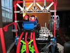
http://i.imgur.com/7HJeR4k.jpg <- wheel holder with ball bearings attached
Cedar Point Ride Ops
2013 - Maverick
2014 - Cedar Downs and Cadillac Cars Supervisor
I'm building a thing! http://www.sscoaster...m-launch-16194/
#53
Posted 24 October 2014 - 02:12 PM
I've just about finished the design of my stepper motors, and have bought the iron stock for them. They're not going to be nearly as precise as pro grade stepper motors, but I should be able to squeeze out 20 degree steps. I'm putting in a /lot/ of wire in these (about twice as much as a standard stepper motor), so they should have enough torque to move the car. I'm going to be making 12, so I can have 2 as backups. I'm planning on making a solenoid controller for the 3 solenoids (block brakes, final brakes and station gates), and a motor controller for the 10 motor positions. They will be using an AtTiny, in combination with a mosfet(solenoids) or a bridge driver(steppers). I'm going to be using dirty PCBs, because I can buy 10 5cmX5cm boards for $14 (free shipping), with all the bells and whistles. The driver circuitry will only be about $3-4 per board, so I can try and save money.
I'm still working on the driver for the LSM. This is going to be the tricky part, because of the switching speed required, as well as the many inputs that will need to be constantly read along the launch track and their calculations (integration for velocity/position). Currently I'm leaning towards an FPGA, which will give me the I/O capability, as well as a multitude of processing power. If you've never heard of FPGAs, they're basically a chip that you tell it what to BE. Really neat. Plus the one I'll be needing is only 8-15 bucks.
Beginning to program the PLC - ladder logic FTW. I'm using all 32 outputs, as well as 35-36 inputs (not including the launch system sensors).
Finally, if anyone happens to know of a place that's looking for an intern/co-op in the amusement park industry, if you could send them my way I'd appreciate it. I'm looking for my summer internship and my junior year co-ops now!
More to come!
~Gabe
Cedar Point Ride Ops
2013 - Maverick
2014 - Cedar Downs and Cadillac Cars Supervisor
I'm building a thing! http://www.sscoaster...m-launch-16194/
#54
Posted 24 October 2014 - 03:31 PM
(1)- Voyage (2)- X2 (3)- Steel Vengeance (4)- Twisted Colossus (5)- Storm Chaser [6]- Fury 325 (7)- Outlaw Run (8)- Maverick (9)- Magnum XL-200 (10)- Monster
Coaster Count: 174
Park Count: 25
#55
Posted 28 October 2014 - 07:05 PM
#56
Posted 16 December 2014 - 05:13 PM
Instead of using 3d printed materials, I'm going to use parts milled out of 1/4 inch aluminum. (I designed the parts with square edges, but it's meant to be milled out with a 1/16 drill bit)
http://i.imgur.com/TajoWFd.png there will be two of these pieces across from each other, holding the magnets. Because they're milled out of solid aluminum, I don't need nearly as much to prevent bending (unlike 3d printed materials)
http://i.imgur.com/Gyc4ilq.png this is the "rib" of the car. There will be 4 of these, one on each end and two in the center. The back one will have extra metal on the sides to attach the wheel assembly to.
These will be milled hopefully in January when I go back to school.
The PLC program is about 1/2 of the way done. Coding is fun!
More to come over winter break!
~Gabe
Cedar Point Ride Ops
2013 - Maverick
2014 - Cedar Downs and Cadillac Cars Supervisor
I'm building a thing! http://www.sscoaster...m-launch-16194/
#57
Posted 16 December 2014 - 06:48 PM
I am not sure how you're going to get this all to work, but I am sure I will have to pick my jaw off the ground when we finally see it!
1- Time Traveler 2- Magnum XL-200 3- The Voyage 4- Velocicoaster 5-Iron Gwazi 6- Phantom's Revenge 7- The Beast 8- The Legend 9- Tiested Timbers 10- Steel Vengeance
Follow me on Instagram @coastergeek987
Credit Count: 305
#58
Posted 17 January 2015 - 07:14 PM
*Got an Allen Bradley AIC for my PLCs, which will enable me to communicate with the PLCs through my computer's serial port as well as through a raspberry pi's GPIO pins
*Been working on a variable frequency drive, which I hope to have designed by the end of next week
*Ordered a second high power PSU for the system, this one is a multivoltage supply, which I'll be using to drive my motors, as well as the optosensors and VFD controls ( http://d3d71ba2asa5o...odparts (3).jpg )
*Bought an arduino mega for use with the VFD (only cost me 12 bucks, so I won't be too bummed if it burns)
*Got my Darlington transistors for the VFD - these were originally intended for a railgun, but they're able to operate easily at the power levels I want
Sorry I haven't been working on this more, I had a lot of work to do with finals, as well as a secondary project that I was on a time crunch to finish - a raspberry pi powered pip boy from fallout - http://i.imgur.com/n2ezRvk.png As I'm writing this post, my computer is actually processing the pieces so I can 3d print and assemble the bloody thing xD
Once the power supply arrives, I plan on doing a teardown of both (probably a video teardown), to get them ready for operation. I've got a bunch of the design work done for the VFD, but I need to run tests on the response time of my transistors - big honkin heavy ones http://i.imgur.com/ZCZLYiU.jpg
More to come!
Cedar Point Ride Ops
2013 - Maverick
2014 - Cedar Downs and Cadillac Cars Supervisor
I'm building a thing! http://www.sscoaster...m-launch-16194/
#59
Posted 19 January 2015 - 09:27 PM
#60
Posted 23 January 2015 - 01:32 AM
This is a pictoral one, so if you go here, you'll be able to see what I'm talking about
http://i.imgur.com/SsGUQBW.jpg
Reading the scope: The bottom of the screen tells you the voltage/time of the graph. For example, in the first picture, one line in the vertical direction = 5 volts, and one line in the horizontal direction = 500ms (0.5s)
Top left: The transistor works! I was doing all these tests off 5 volts (which helps reduce the risk of me shocking myself while moving test probes around. The yellow trace is the voltage difference across the input and the output of the circuit. When it is high, that means the transistor is blocking, and when it is low (near the blue), the transistor is conducting.
Top right: Beginning frequency tests: The frequency generator outputs a signal at 5 hertz for this test, with the yellow being the trigger (you can't really see the trigger, my bad), and the blue being the output voltage.
Middle left: Higher frequency - the delay in power is beginning to become evident. The speed of the scope has been increased to make it easier to see. Because the power supply being used isn't optimized for switching loads (dosen't have big capacitors on the output), it takes a microsecond or so to reach the full voltage - just in time for the power to cut
Middle right: Super high frequency - 957Hz. I kind of cheated and added an inductor to the circuit, because the voltage wasn't making it past 0.5 volts before being switched off again. (An inductor wants a constant current, so it'll change the voltage to keep the current even). This has the effect of making a kind of waveform - that voltage spike goes to 25 volts.
Bottom left: The super scientific test setup I used. Power supply is just out of frame to the right, the big transistor is the black box with all the wires coming off, and the brown tube is a large resistor. This is used to give the system a load.
Bottom right: My high speed optosensor - this was a bit of a challenge for me, because I had bought them off of ebay last semester, but the seller must have been kicked off, because the purchase wasn't showing in my ebay history. This meant I wasn't able to get a datasheet, so I just grabbed a similar datasheet and hoped for the best. It worked! I actually was able to directly connect it to my arduino mega and read the status of the sensor in real time. I had a video, but I was holding my phone really weird so the audio track is just a garbled mess of me talking mixed with thumps and scraping xD
Extremely simple circuit with just a 180 ohm resistor to drive the IR led, and a 10k resistor to pull the arduino pin. No extra drive circuitry means that it has a quick response time, which is good as I'm going to need it!
With the right mix of inductors and capacitors, I should be able to make a fairly square wave come out of the transistors. A back of the envelope calculation tells me I'm going to want about 400-600 Hz drive speeds, although because it's a 3 phase inverter this could probably be actually done by cutting the frequency in 1/3 and timing it so the electromagnet is at its optimal power when it's time. The transistors say that they can complete a switch on/switch off movement in 12 microseconds, but I don't think I'd be able to get it to work properly at that speed...
This weekend - going to get some more modeling work done, as well as restart my PLC program (there's some parts that I really don't like). It's a lot easier now that I have a definite variable to use for the size of the sensors!
More to come!
Cedar Point Ride Ops
2013 - Maverick
2014 - Cedar Downs and Cadillac Cars Supervisor
I'm building a thing! http://www.sscoaster...m-launch-16194/